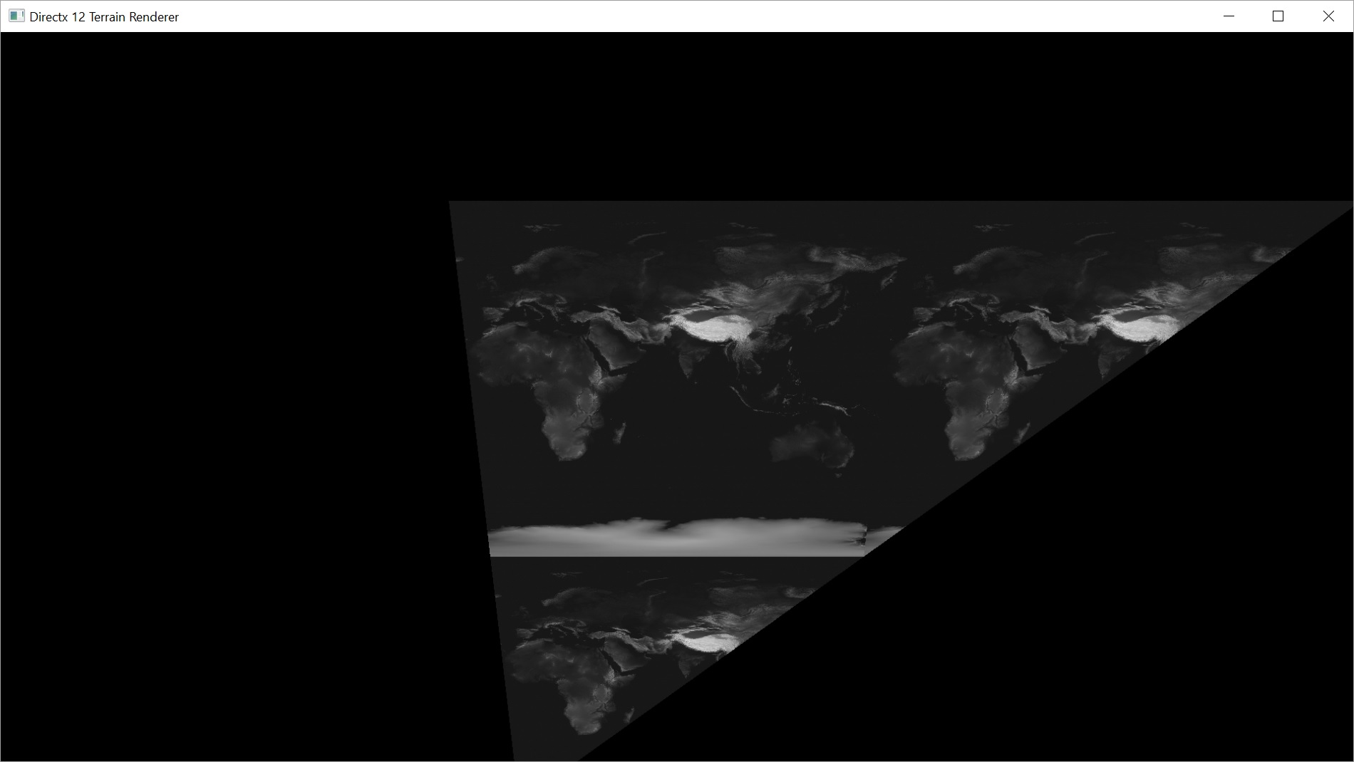
Last time, we finally got our terrain rendered as a black and white 2D image. This time, we want to make some changes and try to get this thing rendering in 3D. So what steps are needed to make this a reality?
- We need to set up a camera with some sort of 3D projection.
- We need to create geometry to represent the height map in 3D.
- We need to pass the geometry and the camera info to our shaders.
- We need to rewrite the shaders to support the new info.
The Camera
In order to make something appear 3D on the screen, we need to transform its vertices with respect to the camera. This is referred to as a projection. There are 2 main projections that get used: Orthographic and Perspective. Orthographic projections are 3D, but objects aren’t affected by their distance from the camera. Objects in the distance appear to be the same size as those in the foreground, instead of being smaller. Perspective projection more closely matches the human eye in that objects are affected by distance. We’ll be using a Perspective projection for this project.
Objects in the scene are made up of vertices. Each vertex can be represented by a 4D vector made up of x, y, z, and w components. I think x, y, and z are fairly intuitive, but w may not be. The reason we have w is in order to have a homogeneous coordinate system. Perspective projection will require it and it also allows us to represent other transformations, like scaling, rotation, and translation (movement along an axis) as matrices that can then be multiplied together.
This article gives a pretty good summary of homogeneous coordinates and how they apply to perspective projection.
This answer on math.stackexchange.com shows why we use 4D vectors and matrices in general to represent 3D.
We want to represent the camera in a way that we can get a matrix that can be used to correctly transform the vertices of our terrain relative to the camera. For that, we’ll need to know our camera’s position in the world, the point the camera is looking towards, and a vector representing the direction ‘up’ relative to the camera.
We’ll also need to decide on a field of view, an aspect ratio, how close to the camera objects can get before we consider them to have passed behind it1, and how far away objects can get before we stop rendering them2.
Once we’ve got all of this information, we can build our matrices.
// build projection matrix
XMMATRIX viewproj = XMMatrixPerspectiveFovLH(XMConvertToRadians(45.0f), (float)w / (float)h, 0.1f, 24000.0f);
XMStoreFloat4x4(&mmProjection, viewproj);

// set starting camera state
mvPos = XMFLOAT4(1024.0f, 1024.0f, 1800.0f, 0.0f);
mvLookAt = XMVector3Normalize(XMFLOAT4(-512.0f, -512.0f, -1800.0f, 0.0f));
mvUp = XMFLOAT4(0.0f, 0.0f, 1.0f, 0.0f);
The first line of the above code creates a projection matrix that will transform objects in the world so that objects at a distance are smaller. As mentioned above, it takes the field of view, aspect ratio (defined by the height and width of our screen), and the near and far planes.
Then we set our camera values that will define our view matrix. The view matrix can be used to transform objects in the world relative to the camera. The variable mvPos stores the position in the world where our camera is located. The vector describing in what direction we’re pointing is called mvLookAt. The last variable is mvUp, which describes which way is up for the camera. If the camera were upside down, mvUp would be pointing down.
We don’t need to store the view matrix, and we’ll see in later posts that it will change often, so we don’t create the matrix in the constructor. We have a separate function that builds and returns a combined view/projection matrix that can be passed to objects to fully transform them.
// combine the view and projection matrices and transpose the result
XMFLOAT4X4 Camera::GetViewProjectionMatrixTransposed() {
	XMVECTOR look = XMLoadFloat4(&mvLookAt);
	XMVECTOR up = XMLoadFloat4(&mvUp);
	XMVECTOR camera = XMLoadFloat4(&mvPos);
	XMVECTOR target = camera + look; // add camera position plus target direction to get target location for view matrix function
	XMMATRIX view = XMMatrixLookAtLH(camera, target, up)
	XMMATRIX proj = XMLoadFloat4x4(&mmProjection);
	XMMATRIX viewproj = XMMatrixTranspose(view * proj);
	XMFLOAT4X4 final;
	XMStoreFloat4x4(&final, viewproj);
	return final;
}
This function combines the view and projection matrices into one matrix. We don’t currently need either matrix on its own so it makes sense to combine it now. The reason we are transposing the matrix is because the GPU prefers column-major order versus the row-major order the XMMATRIX type uses.
Unless explicitly specified, matrices will be packed in column-major order on input and output from the shader. This is generally more efficient, since it allows vector-matrix multiplication to be performed using a series of dot-products.
Quote from this MSDN document
I think this link does a pretty good job of explaining the difference between row-major order and column-major order.
With this function, we’ve got all we need from the camera.
Creating a mesh for the Height map
In order to have a mesh to pass into the shaders, we’re going to need to create a bunch of triangles. For the sake of efficiency, we don’t want to duplicate vertices, so we’ll make an array of vertices and an array of indices that describe, in order, the triangles of our mesh.
First off, my Vertex is made up of just a position (x, y, z). We could calculate vertex normals3 once on the CPU and then upload that information with the position, but I know that when I get to tessellation, I’m likely going to need to calculate normals dynamically anyway, so we may as well do it now.
Since we’re just worried about the position, and we know we’re creating a regular grid, building the array of vertices is pretty easy. I’m defining the z coordinate as the height. Others may use y instead. As far as I know, there’s no really good reason to choose one over the other.
I could easily set the z value here, but I decided I’ll just set it in the shader. I may revisit this at a later date and see if it saves much. I know it would save 1 texture load per vertex. I just don’t know if it will really matter.
// Create a vertex buffer
int arrSize = height * width;

Vertex *vertices = new Vertex[arrSize];
for (int y = 0; y < height; ++y) {
	for (int x = 0; x < width; ++x) {
		vertices[y * width + x].position = XMFLOAT3((float)x, (float)y, 0.0f);
	}
}
Loading the vertex buffer to the GPU is pretty much the same as loading the height map texture was last week, so we’ll just look at the new bits.
int buffSize = sizeof(Vertex) * arrSize;

GFX->CreateCommittedBuffer(mpVertexBuffer, mpUploadVB, &CD3DX12_RESOURCE_DESC::Buffer(buffSize));
mpVertexBuffer->SetName(L"Vertex buffer heap");
mpUploadVB->SetName(L"Vertex buffer upload heap");

vertexData.pData = vertices;
vertexData.RowPitch = buffSize;
vertexData.SlicePitch = buffSize;

UpdateSubresources(cmdList, mpVertexBuffer, mpUploadVB, 0, 0, 1, &vertexData);
cmdList->ResourceBarrier(1, &CD3DX12_RESOURCE_BARRIER::Transition(mpVertexBuffer, D3D12_RESOURCE_STATE_COPY_DEST, D3D12_RESOURCE_STATE_VERTEX_AND_CONSTANT_BUFFER));

// create the vertex buffer view
mVBV.BufferLocation = mpVertexBuffer->GetGPUVirtualAddress();
mVBV.StrideInBytes = sizeof(Vertex);
mVBV.SizeInBytes = buffSize;
There’s not much to say about this. We don’t need to define a texture at all. We just say how many bytes we need to store our vertices in. Then we schedule the copy. Creating a view is simple and will be used later to tell the GPU to use this vertex buffer.
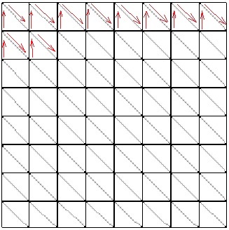
Creating an index buffer is identical to the vertex buffer, except in the building of the array of indices, itself. That’s a little tricky. I decided to go with Triangle Strips. The MSDN documentation has a nice page on primitive topology that demonstrates the order you need to place your indices in.
Our strips will run right-to-left along the x-axis. You’ll notice in the image that we actually start on the second row of the grid and then go up. I did this to match my triangle wrapping to that found on the MSDN page linked above for a triangle strip.
Once we get to the end of the strip, we can’t just end the strip and start another one. We can only pass one long strip to the GPU, so we’ll make some degenerate triangles to get back to the start. A degenerate triangle is a triangle with an area of zero.
The degenerate triangles will get us back to the start of the next strip and we can repeat the process until we’ve created the entire grid.
int stripSize = width * 2;
int numStrips = height - 1;
arrSize = stripSize * numStrips + (numStrips - 1) * 4; // degenerate triangles

UINT* indices = new UINT[arrSize];
int i = 0;
for (int s = 0; s < numStrips; ++s) {
	int m = 0;
	for (int n = 0; n < width; ++n) {
		m = n + s * width;
		indices[i++] = m + width;
		indices[i++] = m;
	}
	if (s < numStrips - 1) { // create indices for degenerate triangles to get us back to the start.
		indices[i++] = m;
		indices[i++] = m - width + 1;
		indices[i++] = m - width + 1;
		indices[i++] = m - width + 1;
	}
}
This page has a slightly different method which would shave a few indices off of my implementation and is probably a little simpler to follow. Where I go top-down, he goes bottom-up, so he doesn’t need to start on the second row and backtrack. He also alternates building his strips left-to-right, and then right-to-left. This eliminates a couple of indices from each pass as he requires fewer degenerate triangles.
I haven’t updated my code yet, but I likely will at some point.
I’m not going to bother posting the code for actually creating the index buffer. As I said above, it is identical to creating the vertex buffer, except you use D3D12_RESOURCE_STATE_INDEX_BUFFER in place of D3D12_RESOURCE_STATE_VERTEX_AND_CONSTANT_BUFFER.
Getting the new data to the GPU
Technically, we’ve already loaded the vertex buffer and index buffer onto the GPU, but we still need to load the view/projection matrix from the camera onto the GPU, and we need to rewrite our root signature and pipeline state object to support the new data.
For the view/projection matrix, we will create a constant buffer. We’re also going to include the height and width of the height map in the buffer, because why not? Maybe it’ll be useful.
Since constant buffers and shader resources can be referenced by the same descriptor heap, we’re going to reuse the SRV heap we created for the height map texture.
// create the SRV heap that points at the heightmap and CBV.
srvHeapDesc.NumDescriptors = 2;
srvHeapDesc.Type = D3D12_DESCRIPTOR_HEAP_TYPE_CBV_SRV_UAV;
srvHeapDesc.Flags = D3D12_DESCRIPTOR_HEAP_FLAG_SHADER_VISIBLE;
GFX->CreateDescriptorHeap(&srvHeapDesc, mpSRVHeap);
mpSRVHeap->SetName(L"CBV/SRV Heap");

mSRVDescSize = GFX->GetDescriptorHandleIncrementSize(D3D12_DESCRIPTOR_HEAP_TYPE_CBV_SRV_UAV);
The only change from the 2D version is that here we are saying there are 2 descriptors in the heap instead of just one. Interestingly, I can say there are 2 here, but leave everything else the same and the 2D code still works. It just doesn’t define the second descriptor. Since the shaders don’t attempt to reference it, we’re all good.
We also grab the size of the descriptor handle that our device uses. Different devices can use different sizes and we’ll need it to define where the constant buffer’s reference is relative to that of the texture.
Once we’ve made room in our descriptor heap, we can create our constant buffer. While we’re technically passing in static data, normally the view/projection matrix (and potentially other information) would need to be updated pretty much every frame. So, unlike the other buffers we’ve created to date, this one will reside solely in an upload buffer. We won’t create a default buffer at all for it.
// create a constant buffer to contain shader values
void Terrain::CreateConstantBuffer(Graphics *GFX) {
	D3D12_DESCRIPTOR_HEAP_DESC heapDesc = {};
	D3D12_CONSTANT_BUFFER_VIEW_DESC	cbvDesc = {};
	CD3DX12_RANGE readRange(0, 0); // we won't be reading from this resource
	UINT64 buffSize = sizeof(ConstantBuffer);

	// Create an upload buffer for the CBV
	GFX->CreateBuffer(mpCBV, &CD3DX12_RESOURCE_DESC::Buffer(buffSize));
	mpCBV->SetName(L"CBV");

	// Create the CBV itself
	cbvDesc.BufferLocation = mpCBV->GetGPUVirtualAddress();
	cbvDesc.SizeInBytes = (buffSize + 255) & ~255; // CB size is required to be 256-byte aligned.

	CD3DX12_CPU_DESCRIPTOR_HANDLE srvHandle(mpSRVHeap->GetCPUDescriptorHandleForHeapStart(), 1, mSRVDescSize);

	GFX->CreateCBV(&cbvDesc, srvHandle);

	// initialize and map the constant buffers.
	// per the DirectX 12 sample code, we can leave this mapped until we close.
	ZeroMemory(&mCBData, sizeof(mCBData));

	if (FAILED(mpCBV->Map(0, &readRange, reinterpret_cast<void**>(&mpCBVDataBegin)))) {
		throw (GFX_Exception("Failed to map CBV in Terrain."));
	}
}

void Graphics::CreateBuffer(ID3D12Resource*& buffer, D3D12_RESOURCE_DESC* texDesc) {
	if (FAILED(mpDev->CreateCommittedResource(&CD3DX12_HEAP_PROPERTIES(D3D12_HEAP_TYPE_UPLOAD), D3D12_HEAP_FLAG_NONE,
		texDesc,
		D3D12_RESOURCE_STATE_GENERIC_READ, nullptr, IID_PPV_ARGS(&buffer)))) {
		throw GFX_Exception("Failed to create buffer.");
	}
}

// Create a constant buffer view
void Graphics::CreateCBV(D3D12_CONSTANT_BUFFER_VIEW_DESC* desc, D3D12_CPU_DESCRIPTOR_HANDLE handle) {
	mpDev->CreateConstantBufferView(desc, handle);
}
Rather than creating the upload heap and scheduling a copy of data using UpdateSubResources(), this time we actually map the location in memory where the GPU is storing the data to a location where we’ll store the data in system memory. This way, we can just copy our values into the location in system memory and the GPU will upload that data automatically every frame.
Our root signature looks only slightly different. We just need to add an entry to the descriptor table for the constant buffer. We also need to tell the GPU to expect an input layout for the vertices we’re passing it.
// set up the Root Signature.
// create a descriptor table with 2 entries for the descriptor heap containing our SRV to the heightmap and our CBV.
ranges[0].Init(D3D12_DESCRIPTOR_RANGE_TYPE_SRV, 1, 0);
paramsRoot[0].InitAsDescriptorTable(1, &ranges[0]);

// create a root parameter for our cbv
ranges[1].Init(D3D12_DESCRIPTOR_RANGE_TYPE_CBV, 1, 0);
paramsRoot[1].InitAsDescriptorTable(1, &ranges[1], D3D12_SHADER_VISIBILITY_VERTEX);

// create our texture sampler for the heightmap.
descSamplers[0].Init(0, D3D12_FILTER_MIN_MAG_MIP_LINEAR);

// It isn't really necessary to deny the other shaders access, but it does technically allow the GPU to optimize more.
rootDesc.Init(_countof(paramsRoot), paramsRoot, 1, descSamplers, D3D12_ROOT_SIGNATURE_FLAG_DENY_HULL_SHADER_ROOT_ACCESS | D3D12_ROOT_SIGNATURE_FLAG_DENY_DOMAIN_SHADER_ROOT_ACCESS | D3D12_ROOT_SIGNATURE_FLAG_DENY_GEOMETRY_SHADER_ROOT_ACCESS | D3D12_ROOT_SIGNATURE_FLAG_ALLOW_INPUT_ASSEMBLER_INPUT_LAYOUT);
GFX->CreateRootSig(&rootDesc, mpRootSig3D);
The last part of our initialization is the pipeline state object. We’re still compiling a vertex shader and a pixel shader, so that code doesn’t change, other than pointing to a different file for each.
For the PSO, we need to add an input layout. We’re also going to turn back-face culling on to remove triangles that are pointing away from us. The rest can stay the same.
GFX->CompileShader(L"RenderTerrain3dVS.hlsl", VSBytecode, VERTEX_SHADER);
GFX->CompileShader(L"RenderTerrain3dPS.hlsl", PSBytecode, PIXEL_SHADER);

sampleDesc.Count = 1; // turns multi-sampling off. Not supported feature for my card.

// create the pipeline state object
// create input layout.
D3D12_INPUT_ELEMENT_DESC inputLayout[] = {
	{ "POSITION", 0, DXGI_FORMAT_R32G32B32_FLOAT, 0, 0, D3D12_INPUT_CLASSIFICATION_PER_VERTEX_DATA, 0 },
};

inputLayoutDesc.NumElements = sizeof(inputLayout) / sizeof(D3D12_INPUT_ELEMENT_DESC);
inputLayoutDesc.pInputElementDescs = inputLayout;

psoDesc.pRootSignature = mpRootSig3D;
psoDesc.InputLayout = inputLayoutDesc;
psoDesc.VS = VSBytecode;
psoDesc.PS = PSBytecode;
psoDesc.PrimitiveTopologyType = D3D12_PRIMITIVE_TOPOLOGY_TYPE_TRIANGLE;
psoDesc.RTVFormats[0] = DXGI_FORMAT_R8G8B8A8_UNORM;
psoDesc.SampleDesc = sampleDesc;
psoDesc.SampleMask = UINT_MAX;
psoDesc.RasterizerState = CD3DX12_RASTERIZER_DESC(D3D12_DEFAULT);
psoDesc.RasterizerState.CullMode = D3D12_CULL_MODE_BACK;
psoDesc.BlendState = CD3DX12_BLEND_DESC(D3D12_DEFAULT);
psoDesc.NumRenderTargets = 1;
psoDesc.DepthStencilState.DepthEnable = false;
psoDesc.DepthStencilState.StencilEnable = false;

GFX->CreatePSO(&psoDesc, mpPSO3D);
We should now have everything we need initialized. We can move onto actually drawing the terrain.
The Draw Calls
We’re adding just a few lines to our draw calls. We need to pass the view/projection matrix to the terrain object, so the Scene asks the camera for it and hands it to the terrain.
T.Draw3D(mpGFX->GetCommandList(), C.GetViewProjectionMatrixTransposed());
The terrain can then copy the matrix and other values we want into the constant buffer.
mCBData.viewproj = vp;
mCBData.height = mHeight;
mCBData.width = mWidth;
memcpy(mpCBVDataBegin, &mCBData, sizeof(mCBData));
We then set our descriptor heap as before. We also still need to set the Root Descriptor Table, only now we have 2 descriptors to set.
ID3D12DescriptorHeap* heaps[] = { mpSRVHeap };
cmdList->SetDescriptorHeaps(_countof(heaps), heaps);
cmdList->SetGraphicsRootDescriptorTable(0, mpSRVHeap->GetGPUDescriptorHandleForHeapStart());
CD3DX12_GPU_DESCRIPTOR_HANDLE cbvHandle(mpSRVHeap->GetGPUDescriptorHandleForHeapStart(), 1, mSRVDescSize);
cmdList->SetGraphicsRootDescriptorTable(1, cbvHandle);
Finally, we add the vertex and index buffers and make the draw call.
cmdList->IASetPrimitiveTopology(D3D_PRIMITIVE_TOPOLOGY_TRIANGLESTRIP); // describe how to read the vertex buffer.
cmdList->IASetVertexBuffers(0, 1, &mVBV);
cmdList->IASetIndexBuffer(&mIBV);

cmdList->DrawIndexedInstanced(mIndexCount, 1, 0, 0, 0);
From this point, we’ve done everything we need to do in DirectX. Now we just need to look at the shaders. However, we’re already over 2000 words and I’ve got close to 2000 more to say about the shaders, so we’ll call it quits there. The code already includes the shaders, though, so you can take a look. They’re pretty simple.
For the latest version of the project, go to GitHub. Please be aware that the posts are going up on a delay as I am only posting twice a week. I’m coding pretty much every day, so the posts are behind the code. I may have updated the code since I wrote this post.
Traagen