In the last post, we talked about adding support for tessellating our terrain mesh. That tessellation was additive to the existing mesh, meaning that we added smaller triangles than we actually have data for. Eventually, I want to add data, in the form of a detail map, but right now we don’t have that. We’re essentially wasting cycles making geometry that doesn’t add anything, and killing our performance in the process. Today, I’d like to rectify that, and hopefully set up a system that will be able to handle the added detail when we’re ready to add it.
The first part of this will be to reduce the number of triangles in our initial mesh. By reducing the detail in the original mesh, when we tessellate the reduced mesh, we’ll be adding back details that we had lost, rather than just creating unnecessary geometry. So let’s start simple. Let’s leave our tessellation alone, with tessellation factors all equal to 4. And let’s reduce our initial mesh’s vertex density by the same amount. So for a 2048×2048 height map, we’ll generate a 512×512 vertex mesh that is stretched over the same area.
// Create a vertex buffer
mHeightScale = (float)mWidth / 4.0f;
int tessFactor = 4;
int scalePatchX = mWidth / tessFactor;
int scalePatchY = mHeight / tessFactor;

// create a vertex array 1/4 the size of the height map in each dimension,
// to be stretched over the height map
int arrSize = (int)(scalePatchX * scalePatchY);
maVertices = new Vertex[arrSize];
for (int y = 0; y < scalePatchY; ++y) {
	for (int x = 0; x < scalePatchX; ++x) {
		maVertices[y * scalePatchX + x].position = XMFLOAT3((float)x * tessFactor, (float)y * tessFactor, maImage[(y * mWidth * tessFactor + x * tessFactor) * 4] * mHeightScale);
	}
}
int vBuffSize = sizeof(Vertex) * arrSize;
Our index buffer will be pretty much the same, as before, just scaled to the new size of the vertex buffer.
arrSize = (scalePatchX - 1) * (scalePatchY - 1) * 6;
maIndices = new UINT[arrSize];
int i = 0;
for (int y = 0; y < scalePatchY - 1; ++y) {
	for (int x = 0; x < scalePatchX - 1; ++x) {
		maIndices[i++] = x + y * scalePatchX;
		maIndices[i++] = x + 1 + y * scalePatchX;
		maIndices[i++] = x + (y + 1) * scalePatchX;

		maIndices[i++] = x + 1 + y * scalePatchX;
		maIndices[i++] = x + 1 + (y + 1) * scalePatchX;
		maIndices[i++] = x + (y + 1) * scalePatchX;
	}
}
With this, we’re now pretty much back to our original triangle count. But, there is a problem. Our terrain now has jagged edges where there used to be straight edges.
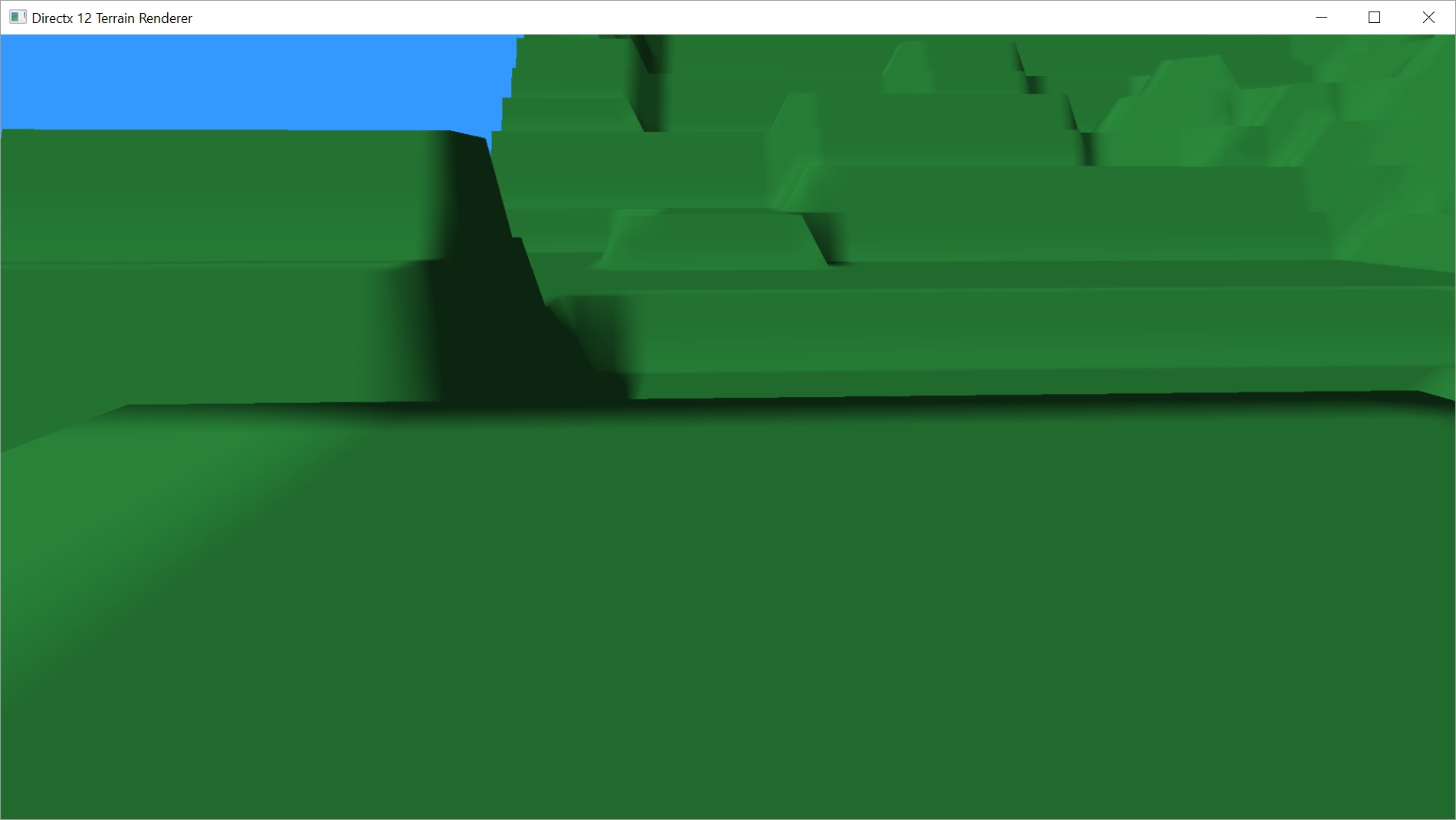
Our 2048×2048 height map. Image rendered before reducing the initial mesh. Note the straight edges.

The same 2048×2048 height map. This time with the reduced mesh and tessellation. Note the broken edges.
My goal had been to reduce the initial mesh and then restore the deleted triangles using tessellation. However, when we create the mesh, we create triangles in a square grid pattern. When we tessellate, we are tessellating those triangles such that the new triangles don’t fall on the square grid anymore.

Note how the triangles no longer form a square grid after tessellation.
So now our triangles no longer line up with the height map. Vertices are now sampling between pixels and we’re having to interpolate the height values. That’s probably not a big deal on a more organic map than this particular one, but if it’s not correct for this one, then it isn’t correct for any.
Luckily, the fix for this is pretty straight forward. We’ll just switch from sending a triangle mesh to sending a quad mesh. Our vertex buffer won’t change at all. We’ll just have to rewrite our index buffer slightly.
arrSize = (scalePatchX - 1) * (scalePatchY - 1) * 4;
maIndices = new UINT[arrSize];
int i = 0;
for (int y = 0; y < scalePatchY - 1; ++y) {
	for (int x = 0; x < scalePatchX - 1; ++x) {
		UINT vert0 = x + y * scalePatchX;
		UINT vert1 = x + 1 + y * scalePatchX;
		UINT vert2 = x + (y + 1) * scalePatchX;
		UINT vert3 = x + 1 + (y + 1) * scalePatchX;
		maIndices[i++] = vert0;
		maIndices[i++] = vert1;
		maIndices[i++] = vert2;
		maIndices[i++] = vert3;
	}
}
We’ll also need to change a line in our draw call to use the new topology type.
cmdList->IASetPrimitiveTopology(D3D_PRIMITIVE_TOPOLOGY_4_CONTROL_POINT_PATCHLIST);
There’s also a few quick changes to our Hull and Domain shaders.
// Our hull shader. I left some stuff out to simplify.
// Output patch constant data.
struct HS_CONSTANT_DATA_OUTPUT
{
	float EdgeTessFactor[4]			: SV_TessFactor; // ***changed from 3
	float InsideTessFactor[2]		: SV_InsideTessFactor; // ***changed from 1
};

#define NUM_CONTROL_POINTS 4 // ***changed from 3

// Patch Constant Function
HS_CONSTANT_DATA_OUTPUT CalcHSPatchConstants(
	InputPatch<VS_OUTPUT, NUM_CONTROL_POINTS> ip,
	uint PatchID : SV_PrimitiveID)
{
	HS_CONSTANT_DATA_OUTPUT output;

	// Insert code to compute output here
	output.EdgeTessFactor[0] = 4;
	output.EdgeTessFactor[1] = 4;
	output.EdgeTessFactor[2] = 4;
	output.EdgeTessFactor[3] = 4; // ***new edge tessellation factor
	output.InsideTessFactor[0] = 4;
	output.InsideTessFactor[1] = 4; // ***new inside tessellation factor

	return output;
}

[domain("quad")] // ***changed from [domain("tri")]
[partitioning("fractional_even")]
[outputtopology("triangle_cw")]
[outputcontrolpoints(4)] // ***changed from [outputcontrolpoints(3)]
[patchconstantfunc("CalcHSPatchConstants")]
HS_CONTROL_POINT_OUTPUT main(
	InputPatch<VS_OUTPUT, NUM_CONTROL_POINTS> ip,
	uint i : SV_OutputControlPointID,
	uint PatchID : SV_PrimitiveID )
{
	HS_CONTROL_POINT_OUTPUT output;

	// Insert code to compute Output here
	output.worldpos = ip[i].worldpos;
	output.tex = ip[i].tex;

	return output;
}
// Our domain shader. I left some stuff out to simplify.
// Output patch constant data.
struct HS_CONSTANT_DATA_OUTPUT
{
	float EdgeTessFactor[4]			: SV_TessFactor; // e.g. would be [4] for a quad domain
	float InsideTessFactor[2]		: SV_InsideTessFactor; // e.g. would be Inside[2] for a quad domain
};

#define NUM_CONTROL_POINTS 4 // ***changed from 3

[domain("quad")] // ***changed from [domain("tri")]
DS_OUTPUT main(
	HS_CONSTANT_DATA_OUTPUT input,
	float2 domain : SV_DomainLocation, // ***changed from float3
	const OutputPatch<HS_CONTROL_POINT_OUTPUT, NUM_CONTROL_POINTS> patch)
{
	DS_OUTPUT output;
	// ***changed from barycentric to (u,v) coordinates. Now need to use bilinear interpolation to find the new points.
	output.worldpos = lerp(lerp(patch[0].worldpos, patch[1].worldpos, domain.x), lerp(patch[2].worldpos, patch[3].worldpos, domain.x), domain.y);
	output.tex = lerp(lerp(patch[0].tex, patch[1].tex, domain.x), lerp(patch[2].tex, patch[3].tex, domain.x), domain.y);
	output.worldpos.z = heightmap.SampleLevel(hmsampler, output.tex, 0.0f).x * scale;

	output.pos = float4(output.worldpos, 1.0f);
	output.pos = mul(output.pos, viewproj);
	return output;
}
I didn’t bother to take a screen shot at this stage. We’re back to straight edges. We’ve gained a bit of smoothing caused by the fact we’re still linearly interpolating values. The precision of our calculations isn’t going to be exact, so we’re not necessarily landing on perfect integer values. This is actually ok. A bit of smoothing works and won’t be much of an issue once we add a detail map and displacement mapping later.
Our performance is also back to where it was before we had added tessellation, roughly anyway. This 2048×2048 height map takes about 2-3ms to render, which works out to around 370fps. Comparable to the 750fps we were getting with the 1024×1024 height map we looked at last time. Before we reduced the density of the initial mesh, we were looking at about 35ms drawing time, or just under 30fps.
Dynamic Level of Detail
Adding dynamic LOD to the terrain mesh was surprisingly easy. I’m following the chapter on this in Introduction to 3D Game Programming with DirectX 11 by Frank Luna. He provides plenty of code but if you’re not looking at the demo project on the included CD, there’s still a bit of work you need to do to translate it to your own code.
The necessary change occurs in the hull shader.
// We add the following function to calculate what tessellation factor to use at
// what distance. Factors used are all factors of 2. ie 1, 2, 4, 8, 16, 32, 64 (64 being max)
// because we're using [partitioning("fractional_even")], the tessellator should automatically
// interpolate between these values, taking care of potential popping concerns.
float CalcTessFactor(float3 p) {
	float d = distance(p, eye);

	float s = saturate((d - 16.0f) / (512.0f - 16.0f));
	return pow(2, (lerp(6, 0, s)));
}

// Patch Constant Function
HS_CONSTANT_DATA_OUTPUT CalcHSPatchConstants(
	InputPatch<VS_OUTPUT, NUM_CONTROL_POINTS> ip,
	uint PatchID : SV_PrimitiveID)
{
	HS_CONSTANT_DATA_OUTPUT output;

	// tessellate based on distance from the camera.
	// compute tess factor based on edges.
	// compute midpoint of edges.
	float3 e0 = 0.5f * (ip[0].worldpos + ip[2].worldpos);
	float3 e1 = 0.5f * (ip[0].worldpos + ip[1].worldpos);
	float3 e2 = 0.5f * (ip[1].worldpos + ip[3].worldpos);
	float3 e3 = 0.5f * (ip[2].worldpos + ip[3].worldpos);
	float3 c = 0.25f * (ip[0].worldpos + ip[1].worldpos + ip[2].worldpos + ip[3].worldpos);

	output.EdgeTessFactor[0] = CalcTessFactor(e0);
	output.EdgeTessFactor[1] = CalcTessFactor(e1);
	output.EdgeTessFactor[2] = CalcTessFactor(e2);
	output.EdgeTessFactor[3] = CalcTessFactor(e3);
	output.InsideTessFactor[0] = CalcTessFactor(c);
	output.InsideTessFactor[1] = output.InsideTessFactor[0];

	return output;
}
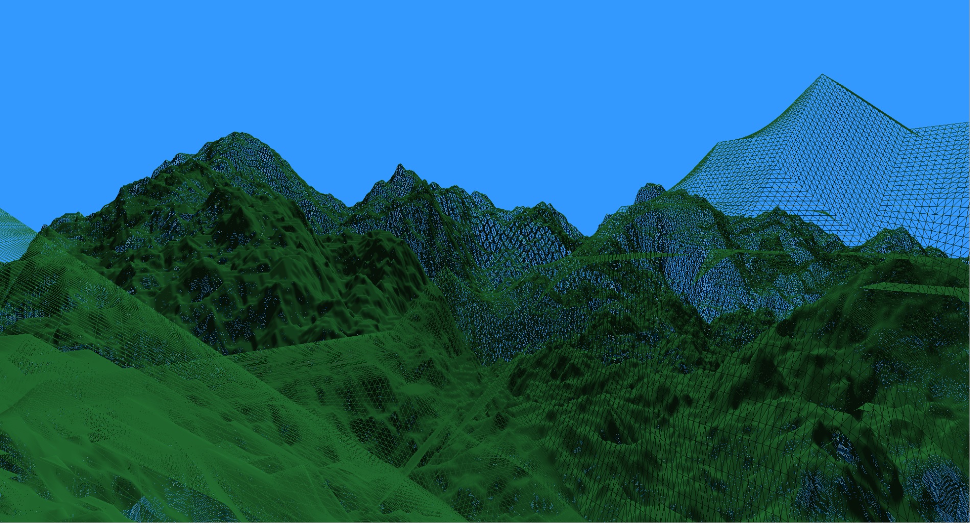
With this change, we’re now rendering patches that start out at 4×4 in the initial mesh and can wind up being tessellated down to 1/16×1/16 for patches nearest the camera. I chose my near and far distances arbitrarily. I’ll need to change them from being hard coded, but you can see I’m currently using a near distance of 16 and a far distance of 512. So any edge whose midpoint is closer to the camera than 16 units is tessellated 64 times. Anything farther away than 512 units is not tessellated at all.
With these settings, our time to render a frame peaks at about 5.1ms, roughly 197fps. I can see absolutely no loss of detail in the distance, there is no discernable popping, and here’s a shot of the triangle density up close.

Once I’ve added shadows in, if we dip below our 120fps threshold, I may make the size of the initial mesh smaller. This will impact how dense the close up stuff is, but would eliminate a ton of vertices and probably speed things up further. As proof, I tried setting the initial mesh to 8×8 and the frame rate dropped below 2ms. At the slowest point, it was running at over 600fps and we still had 1/8×1/8 density up close.
With those kinds of numbers, is it even worth it to try and optimize further with frustum culling? We won’t know for sure until we try it!
We’ll cover that in the next post.
You can find the latest code on GitHub.
Traagen