So what is view frustum culling? Here’s a pretty decent tutorial. Basically, the view frustum is the 3-dimensional volume of the scene that you can actually see on screen. Any part of the world that isn’t in that volume does not need to be drawn, so we can discard or cull it.
In most projects, when you have numerous objects that are constantly being created and destroyed and moving in and out of view, you would have some sort of data structure, often a quad- or octree, that sorts your world. So you would do a lot of your culling on the CPU so that you can limit what gets sent to the GPU.
In our case, the only thing in our world is the terrain and it gets sent to the GPU once and is rendered every frame. We’re going to do our frustum culling on the GPU. Technically, the GPU does its own culling when it goes to rasterize the triangles. At that stage, it will clip everything so it only draws the triangles that are on the screen, basically a 2D version of frustum culling. But before it does that, it has to tessellate and displace the vertices of the mesh. We want to toss out any patches we can before they get tessellated, so we’re going to modify our hull shader to perform frustum culling.
Calculating the View Frustum
Before we can update our shader, we’re going to need the view frustum itself. In the form we’re going to be using, it is made up of six planes: left, right, top, bottom, near, far. We’re going to have our camera object calculate these planes each frame from our current view and projection matrices.
Remember that we don’t store the view matrix, so we’ll need to calculate it based on our position and orientation, then multiply it with the projection matrix to give us our combined final matrix.
// Return the 6 planes forming the view frustum. Stored in the array planes.
void Camera::GetViewFrustum(XMFLOAT4 planes[6]) {
	// rotate camera based on yaw, pitch, and roll.
	XMVECTOR look = XMLoadFloat4(&mvLookAt);
	XMVECTOR up = XMLoadFloat4(&mvUp);
	XMVECTOR left = XMLoadFloat4(&mvLeft);
	if (mPitch != 0 || mYaw != 0 || mRoll != 0) {
		float pitch_rad = XMConvertToRadians(mPitch);
		float yaw_rad = XMConvertToRadians(mYaw);
		float roll_rad = XMConvertToRadians(mRoll);

		XMMATRIX rot, rotp, roty, rotr;
		rotp = XMMatrixRotationAxis(left, pitch_rad);
		roty = XMMatrixRotationAxis(up, yaw_rad);
		rotr = XMMatrixRotationAxis(look, roll_rad);
		rot = rotp * roty * rotr;
		look = XMVector3Normalize(XMVector3Transform(look, rot));
		left = XMVector3Normalize(XMVector3Transform(left, rot));
		up = XMVector3Cross(left, look);
	}

	// build view/projection matrix
	XMVECTOR camera = XMLoadFloat4(&mvPos);
	XMVECTOR target = camera + look; // add camera position plus target direction to get target location for view matrix function
	XMMATRIX view = XMMatrixLookAtLH(camera, target, up);
	XMMATRIX proj = XMLoadFloat4x4(&mmProjection);
	XMFLOAT4X4 M;
	XMStoreFloat4x4(&M, view * proj);

	// left
	planes[0].x = M(0, 3) + M(0, 0);
	planes[0].y = M(1, 3) + M(1, 0);
	planes[0].z = M(2, 3) + M(2, 0);
	planes[0].w = M(3, 3) + M(3, 0);

	// right
	planes[1].x = M(0, 3) - M(0, 0);
	planes[1].y = M(1, 3) - M(1, 0);
	planes[1].z = M(2, 3) - M(2, 0);
	planes[1].w = M(3, 3) - M(3, 0);

	// bottom
	planes[2].x = M(0, 3) + M(0, 1);
	planes[2].y = M(1, 3) + M(1, 1);
	planes[2].z = M(2, 3) + M(2, 1);
	planes[2].w = M(3, 3) + M(3, 1);

	// top
	planes[3].x = M(0, 3) - M(0, 1);
	planes[3].y = M(1, 3) - M(1, 1);
	planes[3].z = M(2, 3) - M(2, 1);
	planes[3].w = M(3, 3) - M(3, 1);

	// near
	planes[4].x = M(0, 2);
	planes[4].y = M(1, 2);
	planes[4].z = M(2, 2);
	planes[4].w = M(3, 2);

	// far
	planes[5].x = M(0, 3) - M(0, 2);
	planes[5].y = M(1, 3) - M(1, 2);
	planes[5].z = M(2, 3) - M(2, 2);
	planes[5].w = M(3, 3) - M(3, 2);

	// normalize all planes
	for (auto i = 0; i < 6; ++i) {
		XMVECTOR v = XMPlaneNormalize(XMLoadFloat4(&planes[i]));
		XMStoreFloat4(&planes[i], v);
	}
}
The Bounding Box
We’re also going to need a way to test each quad of the terrain against the view frustum. Since our terrain is aligned with the x, y, and z axes, we can use an Axis Aligned Bounding Box (AABB). Then we can just calculate whether each corner of the bounding box is inside the frustum. If any one corner is within the frustum, then we need to render the whole patch.
Getting the x and y boundaries of the patch is easy, since the patch is defined by the four corner vertices. So all we need to find is the minimum and maximum z values.
// calculate the minimum and maximum z values for vertices between the provided bounds.
XMFLOAT2 Terrain::CalcZBounds(Vertex bottomLeft, Vertex topRight) {
	float max = -100000;
	float min = 100000;
	int bottomLeftX = (int)bottomLeft.position.x * 4;
	int bottomLeftY = (int)bottomLeft.position.y;
	int topRightX = (int)topRight.position.x * 4;
	int topRightY = (int)topRight.position.y * 4;

	for (int y = bottomLeftY; y < topRightY; y += 4) {
		for (int x = bottomLeftX; x < topRightX; x += 4) { float z = maImage[x + y * mWidth] * mHeightScale; if (z > max) max = z;
			if (z < min) min = z;
		}
	}

	return XMFLOAT2(min, max);
}
To get an accurate sense of the minimum and maximum z values, we need to search the height map within the bounds of this particular patch. Remember that the height map is still represented by four floating point numbers, even though we really only use the first one. I’ll probably modify that at some point.
We don’t need to send the x or y bounds to the GPU, but we will add the z bounds as a member of our Vertex structure so we have it for every vertex. We’ll use the same convention used in the DirectX 11 book to store the bounds for each patch in vertex[0] of the patch.
The Shader
Here’s our new patch constant function.
// Patch Constant Function
HS_CONSTANT_DATA_OUTPUT CalcHSPatchConstants(
	InputPatch<VS_OUTPUT, NUM_CONTROL_POINTS> ip,
	uint PatchID : SV_PrimitiveID)
{
	HS_CONSTANT_DATA_OUTPUT output;

	// build axis-aligned bounding box.
	// ip[0] is lower left corner
	// ip[3] is upper right corner
	// get z value from boundsZ variable. Correct value will be in ip[0].
	float3 vMin = float3(ip[0].worldpos.x, ip[0].worldpos.y, ip[0].boundsZ.x);
	float3 vMax = float3(ip[3].worldpos.x, ip[3].worldpos.y, ip[0].boundsZ.y);

	// center/extents representation.
	float3 boxCenter = 0.5f * (vMin + vMax);
	float3 boxExtents = 0.5f * (vMax - vMin);

	if (aabbOutsideFrustumTest(boxCenter, boxExtents, frustum)) {
		output.EdgeTessFactor[0] = 0.0f;
		output.EdgeTessFactor[1] = 0.0f;
		output.EdgeTessFactor[2] = 0.0f;
		output.EdgeTessFactor[3] = 0.0f;
		output.InsideTessFactor[0] = 0.0f;
		output.InsideTessFactor[1] = 0.0f;

		return output;
	} else {

		// tessellate based on distance from the camera.
		// compute tess factor based on edges.
		// compute midpoint of edges.
		float3 e0 = 0.5f * (ip[0].worldpos + ip[2].worldpos);
		float3 e1 = 0.5f * (ip[0].worldpos + ip[1].worldpos);
		float3 e2 = 0.5f * (ip[1].worldpos + ip[3].worldpos);
		float3 e3 = 0.5f * (ip[2].worldpos + ip[3].worldpos);
		float3 c = 0.25f * (ip[0].worldpos + ip[1].worldpos + ip[2].worldpos + ip[3].worldpos);

		output.EdgeTessFactor[0] = CalcTessFactor(e0);
		output.EdgeTessFactor[1] = CalcTessFactor(e1);
		output.EdgeTessFactor[2] = CalcTessFactor(e2);
		output.EdgeTessFactor[3] = CalcTessFactor(e3);
		output.InsideTessFactor[0] = CalcTessFactor(c);
		output.InsideTessFactor[1] = output.InsideTessFactor[0];

		return output;
	}
}
We start by grabbing the minimum and maximum values for our AABB from the member vertices of the current patch. We use this info to calculate the center point of the patch and the distance to move along each axis, plus or minus, to get to each of the eight corners.
We then pass that info to our new function.
// returns true if the box is completely outside the frustum.
bool aabbOutsideFrustumTest(float3 center, float3 extents, float4 frustumPlanes[6]) {
	for (int i = 0; i < 6; ++i) {
		// if the box is completely behind any of the frustum planes, then it is outside the frustum.
		if (aabbBehindPlaneTest(center, extents, frustumPlanes[i])) {
			return true;
		}
	}

	return false;
}
This function is pretty simple. It just loops through each of the six frustum planes and tests the AABB against them.
// returns true if the box is completely behind the plane.
bool aabbBehindPlaneTest(float3 center, float3 extents, float4 plane) {
	float3 n = abs(plane.xyz); // |n.x|, |n.y|, |n.z|

	float e = dot(extents, n); // always positive

	float s = dot(float4(center, 1.0f), plane); // signed distance from center point to plane

	// if the center point of the box is a distance of e or more behind the plane
	// (in which case s is negative since it is behind the plane), then the box
	// is completely in the negative half space of the plane.
	return (s + e) < 0.0f;
}
The plane test is pretty funky. It tests the AABB against the plane to determine if it is on the positive or negative side of the plane. This article has a pretty good breakdown of this method of performing the test, as well as other methods and optimizations.
Weeding out Bugs
At this point, I was sure I should have things working, but when I started up the program, the screen was blank. The entire terrain was getting culled, no matter what. I went through and limited the test to only one plane of the frustum at a time. The terrain appeared to render fine for every plane except the bottom. So all of our vertices are being calculated as below the view frustum?
I double checked the code to confirm the view frustum was correct and that the correct values were being sent to the GPU. They were.
I confirmed my method for getting the minimum and maximum z values for a patch was working. It was definitely returning a minimum and maximum value, and I was assigning it to the vertex array.
I eventually used Visual Studio’s Graphics Debugger to actually look at the values on the GPU, and there I discovered my problem.

I should have reformatted the data better for this. Sorry about that. It’s actually a float3 followed by 2 float2s for each vertex. So, each 7 values, reading left to right, top to bottom, is a vertex. The z bounds are the fourth and fifth value for each vertex. You’ll notice that for every vertex we’re getting -4.3160208e+08. That’s a REALLY negative value. There’s no way that value is ever going to be above our bottom view frustum.
But I confirmed that the vertex array was getting normal values. Why is the GPU getting garbage?
Well, it turns out that when I wrote my CreateMesh method, I create the vertex array, then I upload it to the vertex buffer resource on the GPU, then I create the index array and upload that. Now, when I’m creating my indices for each patch, I also have to find the bounds and set the bounds variable for the vertex. But by the time I’m doing this, I’ve already uploaded the vertex array to the buffer, without setting the bounds variable at all. Hence the crap.
So I fixed that. It was just a matter of moving the vertex buffer resource creation to just after building the index array and calculating the patch bounds.
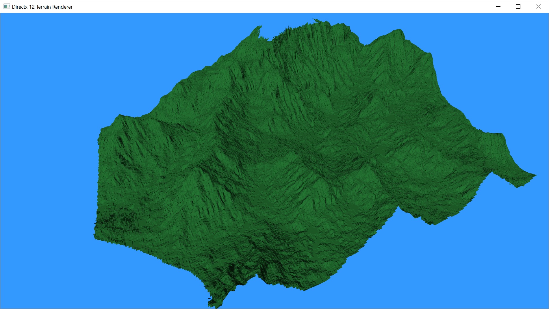
Et voila, the terrain is rendering fine again. And I can tell it is doing the culling because of two more bugs. How helpful.
When I look around the world, I can see patches popping in and out along the edges of the screen.

Left side is missing a patch along the top middle.
On the right, when we tilt the camera up slightly, the missing patch appears.
It felt like the view frustum was too small. But I knew it couldn’t be because we’re using the same view/projection matrix that we use everywhere else. And I already confirmed the values the GPU was getting.
I decided to look more closely at the z bounds calculating code. I quickly realized when I looked at the values it was giving me that it was clipping the top-right values off. I had used < instead of <= in my loops. I quickly fixed this and most of the popping patches went away.
Most, but not all. I was still getting a few patches popping in and out. It always seemed to be along sloped edges, particularly at the top of the slope.
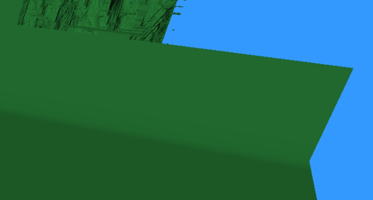
Note how it appears the top right of the slope has been clipped away.
It turns out this was caused by the linear interpolation of our vertices’ height values. Due to that interpolation, which I had said before was fine as it smoothed things out, our final bounding box was actually bigger than I had calculated.
I tried turning off linear interpolation of the height map, but that looks like crap so it pretty much has to stay. So my fix for this ended up being in the same bounds calculating method as the last bug. I expanded the bounding box by one in each direction along the x and y axes for the purposes of calculating the min and max z values. Doing this meant accounting for edges of the height map, but no big deal.
Here’s the final method.
// calculate the minimum and maximum z values for vertices between the provided bounds.
XMFLOAT2 Terrain::CalcZBounds(Vertex bottomLeft, Vertex topRight) {
	float max = -100000;
	float min = 100000;
	int bottomLeftX = bottomLeft.position.x == 0 ? (int)bottomLeft.position.x * 4 : ((int)bottomLeft.position.x - 1) * 4;
	int bottomLeftY = bottomLeft.position.y == 0 ? (int)bottomLeft.position.y * 4 : ((int)bottomLeft.position.y - 1) * 4;
	int topRightX = topRight.position.x * 4 >= mWidth ? (int)topRight.position.x * 4 : ((int)topRight.position.x + 1) * 4;
	int topRightY = topRight.position.y * 4 >= mWidth ? (int)topRight.position.y * 4 : ((int)topRight.position.y + 1) * 4;

	for (int y = bottomLeftY; y <= topRightY; y += 4) {
		for (int x = bottomLeftX; x <= topRightX; x += 4) { float z = maImage[x + y * mWidth] * mHeightScale; if (z > max) max = z;
			if (z < min) min = z;
		}
	}

	return XMFLOAT2(min, max);
}
With that change, frustum culling appears to be working correctly. As far as what you can see on the screen, there has been no change. But performance has improved slightly. The peak render time was 3.8ms, or about 266fps. It fluctuates quite a bit depending on how much of the terrain is actually in front of you. Average is more like 3ms, which is around 320fps.
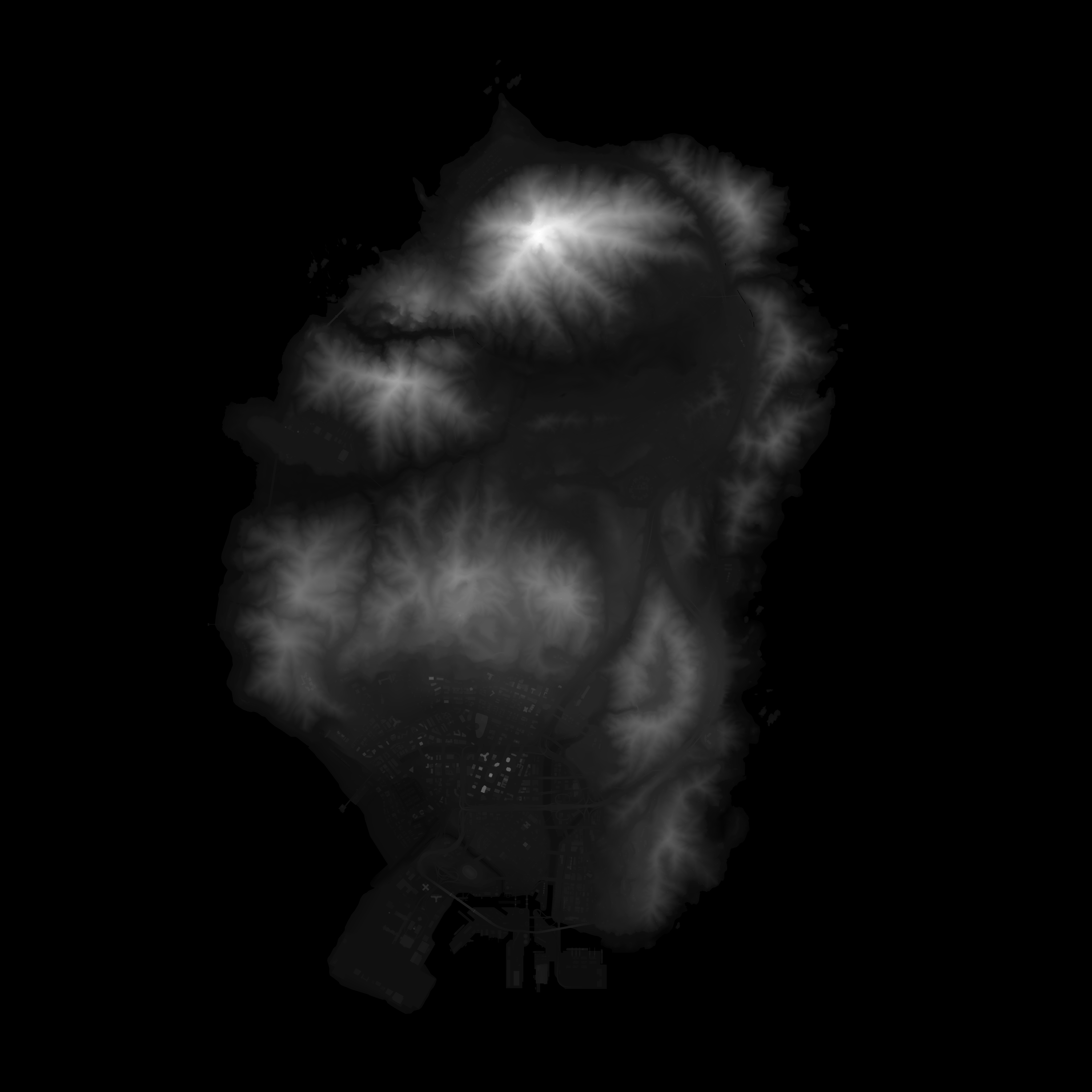
Those numbers are for the 2048×2048 height map featured in the last couple of posts. The 1024×1024 height map mentioned in Part 8 now renders at about 533fps at worst.
I found a new 4096×4096 height map to try. This gets a little slower than I’d like, but that’s pretty easy to expect for something that big. Our worst case was 10.9ms render time, which works out to about 91fps. As we move towards the center of the map, we average out more like 8ms, which is right around 120fps. Adding shadows will slow us down more, so I don’t think we’ll make our best-case performance goal for this large of a map. However, I think we’re in pretty good shape for our 60fps minimum.
I’m going to pause the project here briefly to refactor my code. I’ve realized that certain ways I’ve been doing things won’t work very well long term. I’ll make those changes and go over them next post.
After that, we’ll get our shadows going.
As always, the latest code can be found on GitHub.
Traagen