Originally, in my project introduction, I said I wanted to have two views: a bird’s eye view and a first person view. I realized that it doesn’t make sense to waste time splitting these up when I can just make one set of controls that lets me fly about the world and see the terrain from close up or far away as I please.
This will mean less work over all as we won’t need to write two sets of controls or swap between two view matrices.
In Part 4, we created our Camera class with hard-coded and static variables defining its position and orientation. We now want to be able to move and look around. I’d like to be able to look around freely with the mouse and strafe forwards/backwards, left/right, and up/down with the keyboard. The mouse look will be represented by pitch and yaw. Pitch is the same movement you make when you nod. Yaw is the movement you make when you shake your head side-to-side. I’d like the Camera class to support roll as well, but I don’t intend to use it in this project.
Strafing
Let’s start with strafing because it’s quite a bit easier and faster to write.
Strafing forwards/backwards is easy. We already have a unit vector1 pointing in the direction we’re looking in, mvLookAt. All we have to do is add some multiple of that vector to our current position, and we’ll have moved forward or backward.
Up is a little more complicated. The up vector we defined before was hard-coded to (0.0, 1.0, 0.0), which is generally up, but not up at a 90° angle to the direction we’re looking. If we just used our current mvUp, we wouldn’t actually move up and down relative to where we are looking. We’d move up and down relative to the world up and down. It’s possible this is what we’d want in a different situation. This might make sense in a first person shooter where we might not be able to flip right over and move around upside down; but we’re going for a free-look camera.
To fix this is a two step process. First, we take mvLookAt and our current up vector. If we take the cross product of those two vectors, we will get a vector that is perpendicular to both. In our case we will make a vector pointing left/right. We’ll call it mvLeft.
If we then take mvLeft and mvLookAt and take the cross product again, we’ll get an actual up/down vector we can use as our mvUp. See the above link for more information on how to know which way these vectors are actually pointing.
XMVECTOR look = XMVector3Normalize(XMLoadFloat4(&XMFLOAT4(1.0f, 1.0f, 0.0f, 0.0f)));
XMStoreFloat4(&mvLookAt, look);
XMVECTOR left = XMVector3Cross(look, XMLoadFloat4(&XMFLOAT4(0.0f, 0.0f, 1.0f, 0.0f)));
XMStoreFloat4(&mvLeft, left);
XMVECTOR up = XMVector3Cross(left, look);
XMStoreFloat4(&mvUp, up);
The fact that we just created mvLeft comes in especially handy when we look to strafe left/right. Before doing that, we had no way of knowing which way to move. Now we do.
We now have all three components we need for a strafing function.
// Move the camera along its 3 axes: mvLookAt (forward/backward), mvLeft (left/right), mvUp (up/down)
XMFLOAT4 Camera::Translate(XMFLOAT3 move) {
	// rotate camera based on yaw, pitch, and roll.
	XMVECTOR look = XMLoadFloat4(&mvLookAt);
	XMVECTOR up = XMLoadFloat4(&mvUp);
	XMVECTOR left = XMLoadFloat4(&mvLeft);

	XMVECTOR tmp = XMLoadFloat4(&mvPos);

	tmp += look * move.x + left * move.y + up * move.z;

	XMStoreFloat4(&mvPos, tmp);
	return mvPos;
}
Mouse Look – Roll, Pitch, and Yaw
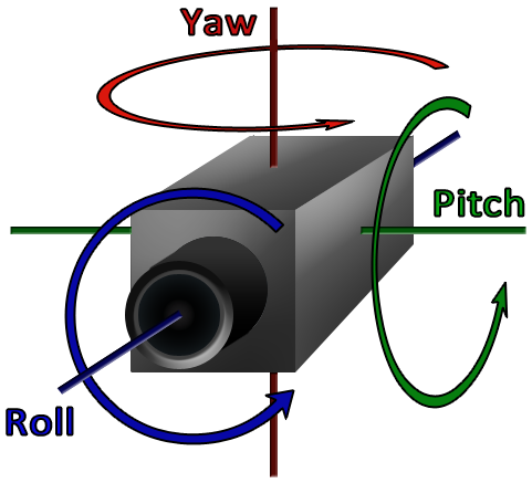
I was hoping to find a good description to link you to which describes roll, pitch, and yaw. Unfortunately, I wasn’t thrilled with what I could find. This image pretty much gets the basic idea across, though. We’ve defined vectors that describe the three axes up/down, left/right, and forward/backward in the previous section. Now, instead of moving along those axes, we’re going to rotate around each of them.
Initially, I took the same approach with rotations that I took with strafing: just rotate our axes about each other every time you rotate and save the results as our new orientation.
Here’s the Pitch() method. As you can see, we rotate mvLookAt around mvLeft. We don’t actually bother rotating mvUp. We just recalculate our up vector with a new cross product. I found this gave better results. Yaw() and Roll() looked exactly the same, except we are rotating around a different axis in each.
void Camera::Pitch(float theta) {
	XMVECTOR look = XMLoadFloat4(&mvLookAt);
	XMVECTOR left = XMLoadFloat4(&mvLeft);
	float rad = XMConvertToRadians(theta);
	XMMATRIX rot = XMMatrixRotationAxis(left, rad);
	look = XMVector3Normalize(XMVector3Transform(look, rot));
	XMVECTOR up = XMVector3Cross(left, look);
	XMStoreFloat4(&mvLookAt, look);
	XMStoreFloat4x4(&mvUp, up);
}
This is essentially the same method I’ve used in past projects and I’ve always wound up with the same odd behaviour. When you combine a bunch of rotations in more than one direction, say a bunch of Yaws and Pitches, you’ll get unwanted rotation about the other axis as well. For instance, if I move the mouse in a circle while having Pitch attached to the y-axis and Yaw on the x-axis, the camera will roll over as I continue the circular motion.
The best answer I could come up with is that this is essentially how compound movements work. In the end, the only real solution I could find was to instead store an accumulation of each angle of rotation and apply all three rotations to the initial orientation when we needed it.
So I’ve added three new variables: mPitch, mYaw, and mRoll, which hold the total angle, in degrees, that we need to rotate by. Our functions now just add any new input to these variables.
void Camera::Pitch(float theta) {
	mPitch += theta;
	mPitch = mPitch > 360 ? mPitch - 360 : mPitch < -360 ? mPitch + 360 : mPitch;
}
Whenever we want to strafe or draw the scene, we need to rotate our axes by all three amounts. We’ll add the following code to both our Translate() and GetViewProjectionMatrixTransposed() methods:
if (mPitch != 0 || mYaw != 0 || mRoll != 0) {
	float pitch_rad = XMConvertToRadians(mPitch);
	float yaw_rad = XMConvertToRadians(mYaw);
	float roll_rad = XMConvertToRadians(mRoll);

	XMMATRIX rot, rotp, roty, rotr;
	rotp = XMMatrixRotationAxis(left, pitch_rad);
	roty = XMMatrixRotationAxis(up, yaw_rad);
	rotr = XMMatrixRotationAxis(look, roll_rad);
	rot = rotp * roty * rotr;
	look = XMVector3Normalize(XMVector3Transform(look, rot));
	left = XMVector3Normalize(XMVector3Transform(left, rot));
	up = XMVector3Cross(left, look);
}
It took me a while to come up with this because there are a number of different methods for performing the rotations. The more efficient seeming approaches involved using XMMatrixRotationRollPitchYaw() or XMQuaternionRotationRollPitchYaw() to create the compound rotation in a single command, instead of creating each separately and multiplying them together. The problem was that those functions apply the rotations as roll first, then pitch, and then yaw. This resulted in the very odd (to me) behaviour of our pitching and yawing being at a 45° angle to where it should be. When I tried to pitch, instead of moving straight up, the camera moved diagonally up and left. Yaw would move up and right instead of directly to the right.
I’m pretty sure this was caused by the order the rotations were being applied in. The order of multiplication controls the order of application. The above order works for this project. Yaw and Pitch work great on the mouse with no rolling and I can strafe along all three axes as expected. I only tested Roll a little bit, but it seems to be working correctly as well.
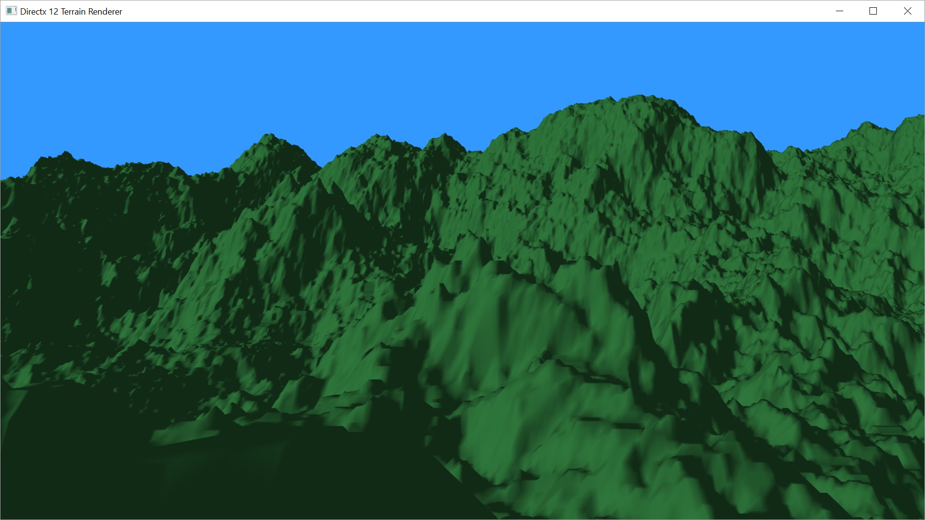
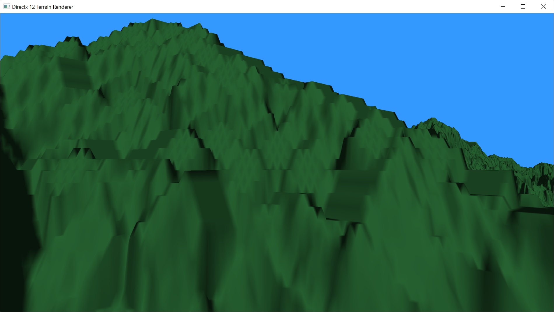
Here’s a shot I took after adding our new camera controls.

Well, actually that picture was taken after I fixed a couple of problems I found.
Depth Testing
Here’s an earlier shot. It’s kind of hard to make out in the shot what’s wrong. I probably should have made a video, but it was such a simple fix, I didn’t bother. I did circle the problem area for you.
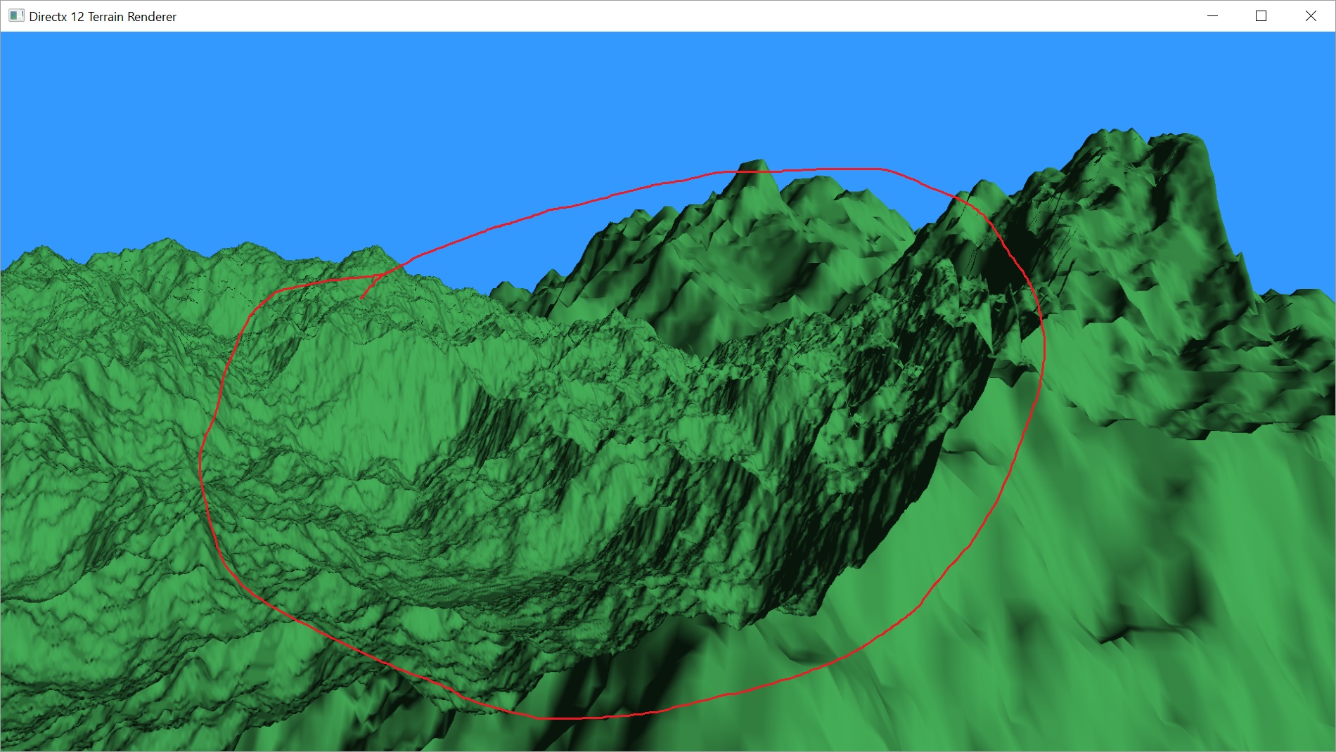
What’s happening, if you can’t see it, is that we can actually see through the terrain. If there’s more terrain behind the bit we’re looking at, we can see the terrain that should be hidden. This has happened because those triangles get rendered later. If you remember from Part 4, we created our vertices and indices starting from (0, 0) and moving away along the positive x and y axes. We also never turned on depth testing because we didn’t need it in 2D and I forgot to enable it when I moved to 3D.
This tutorial will give you a good idea about turning depth testing on.
I added the depth/stencil buffer to my Graphics class and enabled it for my Terrain’s Pipeline State Object.
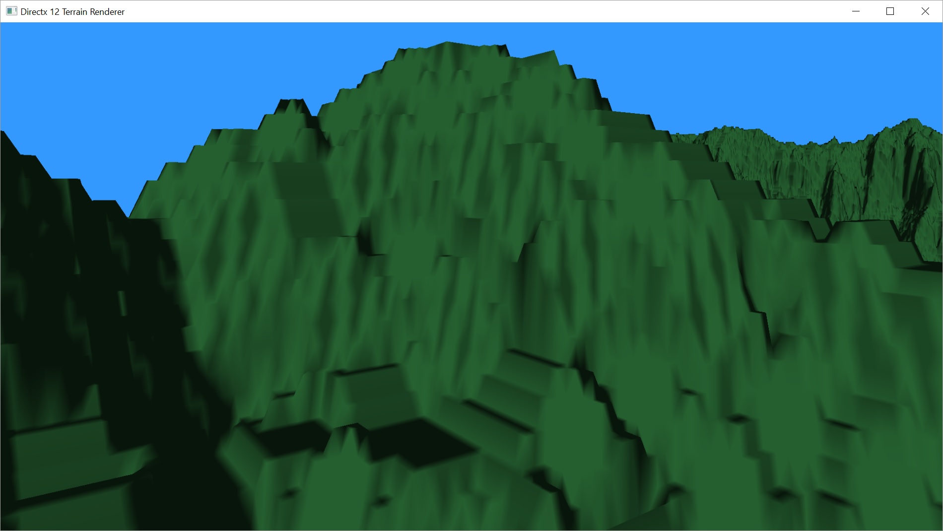
After fixing the problem, here’s a new screenshot from approximately the same angle:

Fixing Our Normals
But that was, unfortunately, not the only problem I stumbled upon now that I could get up close and personal with my terrain. In a few spots in some of the height maps I’ve been using, I found the shading to be doing weird things.
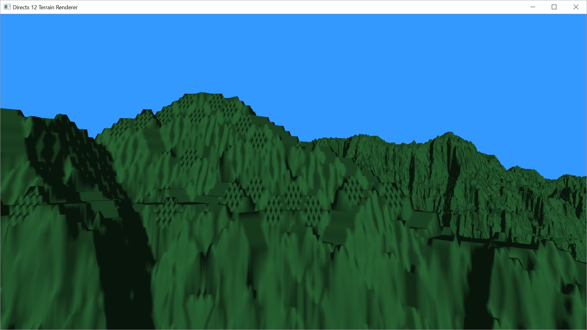
As you can see, where the surface of this terrain should actually be really smooth and flat, we’re getting this weird grid pattern. Now, this isn’t the first time I’ve gotten to this point in building a terrain rendering system, and I don’t remember having these issues. I booted up the old code and, sure enough, I couldn’t find anything similar. But that project actually procedurally generated its height maps so they simply didn’t have flat regions like this. Still, the normal calculation is different, so let’s try it.

In Part 5, we said that our normals would be calculated using four triangles made using the four points directly north, east, south, and west of our working vertex. This is actually a pretty simplistic way of defining them and if we do this for every vertex, you can see that things aren’t going to line up very well.
My older code does slightly more work in that it looks at all 8 surrounding vertices and forms 8 triangles from them, all centered on our working vertex.
VS_OUTPUT main(float3 input : POSITION) {
	VS_OUTPUT output;

	float scale = height / 4;
	float4 mysample = heightmap.Load(int3(input));
	output.pos = float4(input.x, input.y, mysample.r * scale, 1.0f);
	output.tex = float4(input.x / height, input.y / width, output.pos.z, scale);
	output.pos = mul(output.pos, viewproj);

	float zb = heightmap.Load(int3(input.xy + int2(0, -1), 0)).r * scale;
	float zc = heightmap.Load(int3(input.xy + int2(1, -1), 0)).r * scale;
	float zd = heightmap.Load(int3(input.xy + int2(1, 0), 0)).r * scale;
	float ze = heightmap.Load(int3(input.xy + int2(1, 1), 0)).r * scale;
	float zf = heightmap.Load(int3(input.xy + int2(0, 1), 0)).r * scale;
	float zg = heightmap.Load(int3(input.xy + int2(-1, 1), 0)).r * scale;
	float zh = heightmap.Load(int3(input.xy + int2(-1, 0), 0)).r * scale;
	float zi = heightmap.Load(int3(input.xy + int2(-1, -1), 0)).r * scale;

	float x = zg + 2 * zh + zi - zc - 2 * zd - ze;
	float y = 2 * zb + zc + zi - ze - 2 * zf - zg;
	float z = 8.0f;

	output.norm = float4(normalize(float3(x, y, z)), 1.0f);

	output.worldpos = float4(input, 1.0f);

	return output;
}
This wound up working better. But did not eliminate the problem entirely. As you can see in the next image, the diamonds are faded, but still visible.
So why is this happening? Because the triangles I’m using for my normals still don’t match the triangles I’m using for my geometry. For most uses, it probably wouldn’t matter because you’re probably not likely to have terrain like this, but we want it to work properly.
If you again remember back to Part 4, we created our triangles in a uniform pattern, as seen in the image showing our winding pattern. There are actually 6 triangles for every vertex, forming this slanted diamond pattern.

VS_OUTPUT main(float3 input : POSITION) {
	VS_OUTPUT output;

	float scale = height / 4;
	float4 mysample = heightmap.Load(int3(input));
	output.pos = float4(input.x, input.y, mysample.r * scale, 1.0f);
	output.tex = float4(input.x / height, input.y / width, output.pos.z, scale);
	output.pos = mul(output.pos, viewproj);

	float zb = heightmap.Load(int3(input.xy + int2(0, -1), 0)).r * scale;
	float zc = heightmap.Load(int3(input.xy + int2(1, 0), 0)).r * scale;
	float zd = heightmap.Load(int3(input.xy + int2(1, 1), 0)).r * scale;
	float ze = heightmap.Load(int3(input.xy + int2(0, 1), 0)).r * scale;
	float zf = heightmap.Load(int3(input.xy + int2(-1, 0), 0)).r * scale;
	float zg = heightmap.Load(int3(input.xy + int2(-1, -1), 0)).r * scale;

	float x = 2 * zf + zc + zg - zb - 2 * zc - zd;
	float y = 2 * zb + zc + zg - zd - 2 * ze - zf;
	float z = 6.0f;

	output.norm = float4(normalize(float3(x, y, z)), 1.0f);

	output.worldpos = float4(input, 1.0f);

	return output;
}
As you can see, where we used to get a diamond pattern, the surface is now all one colour. As it should be, since it is a flat surface. I’m pretty sure those vertical streaks are correct. That appears to actually be the shape of the surface.
I’m not sure what will happen when we add tessellation. What will the triangles look like then? From what I’ve read, it may not matter. I think you just interpolate the normals you generated in the vertex shader, anyway. At least, until you do something crazy, like displace the new vertices. We’ll get to that soon.
In fact, I think I’d like to tackle tessellation next. I think it makes sense to have all of the geometry dealt with before we look at shadows or colour palettes.
I do want to address a fix for the bug I briefly mentioned way back in Part 1. I don’t think that will be a particularly long post, but I want to get it out of the way before we go further. I’ll address my fix in the next post. The post after that, we’ll begin to implement tessellation.
For the latest version of the project, go to GitHub. Please be aware that the posts are going up on a delay as I am only posting twice a week. I’m coding pretty much every day, so the posts are behind the code. I may have updated the code since I wrote this post.
Traagen