Today, we finally begin looking at tessellation of our terrain. We’re just going to tessellate the whole damn thing with no extra detail. We’ll worry about using the tessellation to add detail and to create a Level of Detail system later. Let’s just get it working, first.
When looking for references for tessellation, I couldn’t find anything at all specifically in DirectX 12. All of the available tutorials and even Microsoft’s own information on MSDN is all for DirectX 11. There is the book ‘Introduction to 3D Game Programming with DirectX 12,’ by Frank Luna, but I have the DirectX 11 version of the book and reviews indicate there’s no real reason to buy the one if you have the other.
I found Frank Luna’s description of tessellation in the DirectX 11 version of his book quite easy to follow. I haven’t read the book cover to cover, so don’t take this as an educated recommendation, but based on this particular chapter, it seems like a good book to start learning with.
There really isn’t much difference between DirectX 11 and 12, as far as tessellation is concerned. Everything in HLSL is identical, and the differences on the Direct3D side are the same sorts of differences we’ve had to go through already to get to this point. Things like preparing the pipeline and compiling the shaders. We’ll look at those steps briefly here, but I think you can get a better explanation of tessellation from those links above.
But let’s dive in.
The first thing we actually need to do before tessellating is to render our terrain in wire frame so that we can actually see the new triangles. This is super simple. We just need to change or add one line in the definition of our pipeline state object.
//psoDesc.RasterizerState.FillMode = D3D12_FILL_MODE_SOLID;
psoDesc.RasterizerState.FillMode = D3D12_FILL_MODE_WIREFRAME;
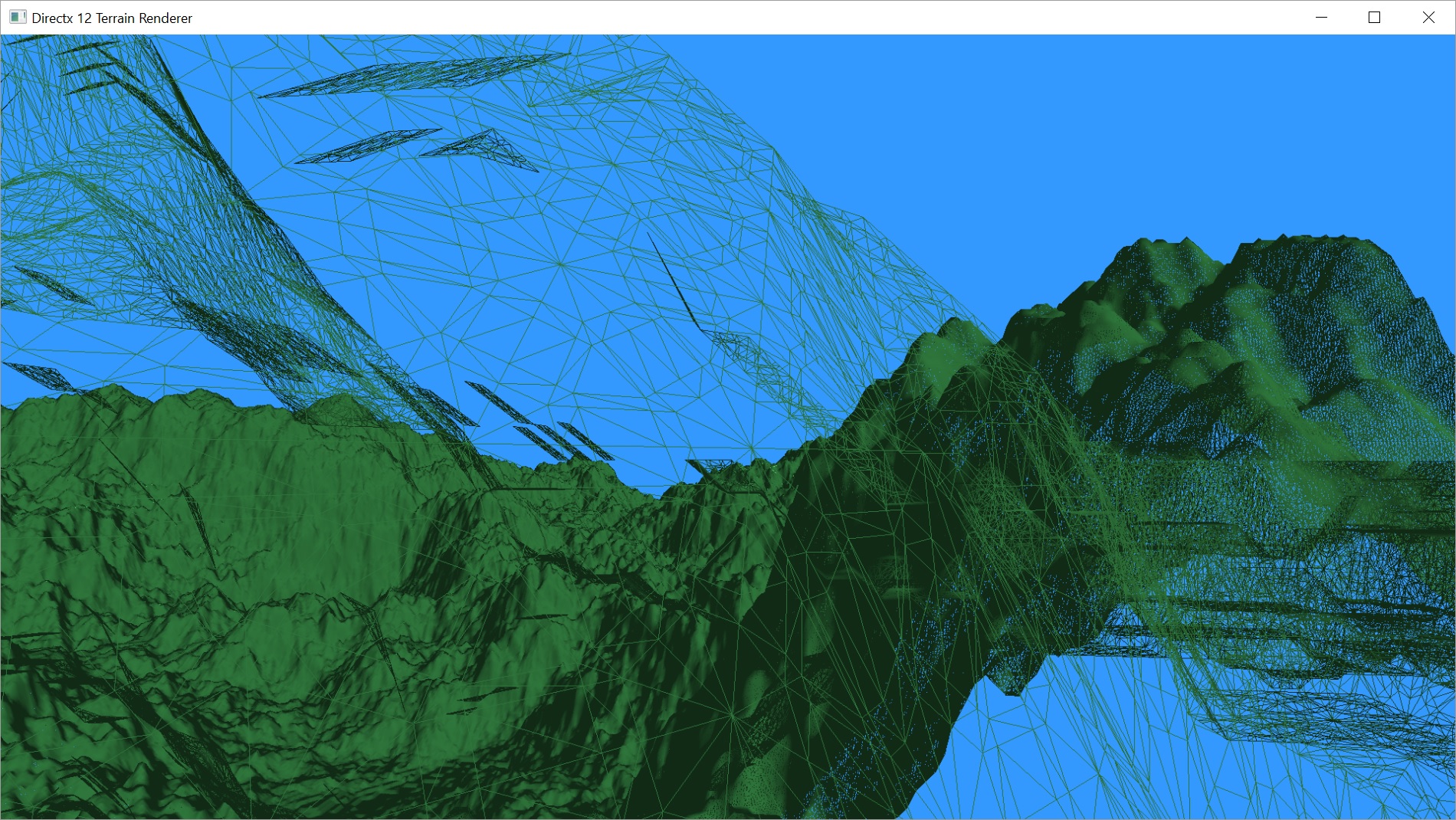
With that line changed, when we render our terrain, it will render in wire frame.
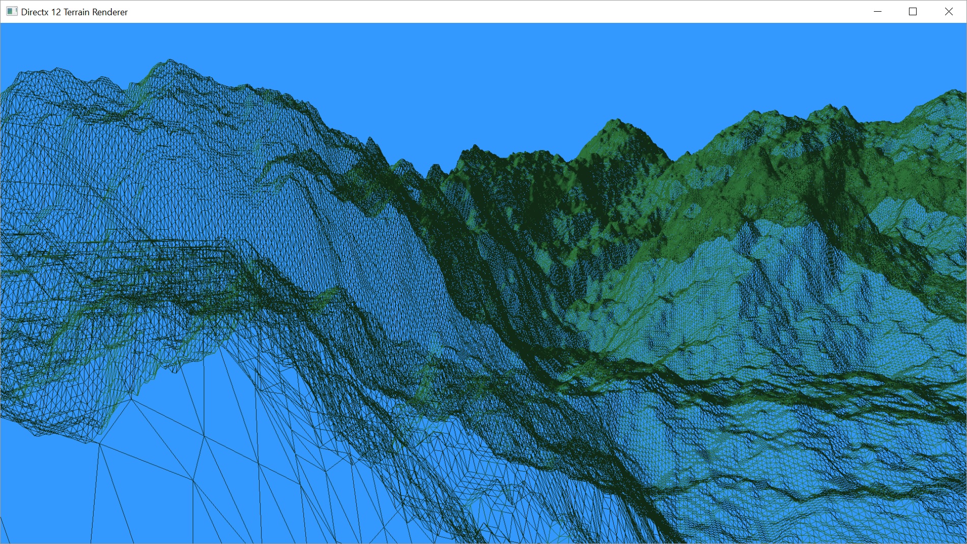
I tried to get a shot where you can see the triangles up close fairly easily. It still looks pretty much solid in the distance because the triangles are so small and densely packed in screen space that there really aren’t any pixels that don’t have an edge crossing them. This is a pretty good argument for a level of detail system. We obviously don’t need that many triangles at that distance. We’ll get to that at a later date.
Adding Tessellation in DirectX 12
Let’s move on and get DirectX ready to go for tessellation. What changes need to happen to our pipeline to get it going?
Actually, not that much needs to change. Firstly, we need two new shaders, the Hull Shader and the Domain Shader. Compiling these shaders is identical to compiling our vertex and pixel shaders.
// Compile the specified shader.
void Graphics::CompileShader(LPCWSTR filename, D3D12_SHADER_BYTECODE& shaderBytecode, ShaderType st) {
	ID3DBlob*	shader;
	ID3DBlob*	err;
	LPCSTR		version;

	switch (st) {
		case PIXEL_SHADER:
			version = "ps_5_0";
			break;
		case VERTEX_SHADER:
			version = "vs_5_0";
			break;
		case GEOMETRY_SHADER:
			version = "gs_5_0";
			break;
		case HULL_SHADER:
			version = "hs_5_0";
				break;
		case DOMAIN_SHADER:
			version = "ds_5_0";
			break;
		default:
			version = ""; // will break on attempting to compile as not valid.
	}

	if (FAILED(D3DCompileFromFile(filename, NULL, NULL, "main", version, D3DCOMPILE_DEBUG | D3DCOMPILE_SKIP_OPTIMIZATION, 0, &shader, &err))) {
		if (shader) shader->Release();
		if (err) {
			throw GFX_Exception((char *)err->GetBufferPointer());
		}
		else {
			throw GFX_Exception("Failed to compile Pixel Shader. No error returned from compiler.");
		}
	}
	shaderBytecode.BytecodeLength = shader->GetBufferSize();
	shaderBytecode.pShaderBytecode = shader->GetBufferPointer();
}
Once we’ve compiled the shaders, we just add them to our pipeline state object. When using a Hull Shader, we must also use a Domain Shader. The tessellation pipeline requires both. Microsoft does a pretty good job of breaking down the pipeline and describing the different stages of tessellation.
When we use these two new shaders, we also have to change our primitive topology type. We are no longer passing triangles to the GPU, we are now passing Patches. In our case, the patches are still triangles, but we are required to make the distinction.
...
GFX->CompileShader(L"RenderTerrainTessVS.hlsl", VSBytecode, VERTEX_SHADER);
GFX->CompileShader(L"RenderTerrainTessPS.hlsl", PSBytecode, PIXEL_SHADER);
GFX->CompileShader(L"RenderTerrainTessHS.hlsl", HSBytecode, HULL_SHADER);
GFX->CompileShader(L"RenderTerrainTessDS.hlsl", DSBytecode, DOMAIN_SHADER);

...

psoDesc.pRootSignature = mpRootSigTes;
psoDesc.InputLayout = inputLayoutDesc;
psoDesc.VS = VSBytecode;
psoDesc.PS = PSBytecode;
psoDesc.HS = HSBytecode;
psoDesc.DS = DSBytecode;
psoDesc.PrimitiveTopologyType = D3D12_PRIMITIVE_TOPOLOGY_TYPE_PATCH;
...
Because we are no longer passing triangles to the GPU, we also need to change a line in our draw function. We were setting our primitive topology to a Triangle Strip. Now we need to set it to a patch list.
cmdList->IASetPrimitiveTopology(D3D_PRIMITIVE_TOPOLOGY_3_CONTROL_POINT_PATCHLIST);
The bad news here is that we just spent a bunch of time building an array of indices based on a triangle strip. If we had just gone with a triangle list in the first place, we’d be sending more data to the gpu, using more bandwidth, but we’d be done now because that same triangle list would double as a 3-control-point patch list. Now we have to rewrite our mesh creation.
// switched to triangle list instead of strip.
// 3 times more memory required.
arrSize = (mWidth - 1) * (mHeight - 1) * 6;
UINT* indices = new UINT[arrSize];
int i = 0;
for (int y = 0; y < mHeight - 1; ++y) {
	for (int x = 0; x < mWidth - 1; ++x) {
		indices[i++] = x + y * mWidth;
		indices[i++] = x + 1 + y * mWidth;
		indices[i++] = x + (y + 1) * mWidth;

		indices[i++] = x + 1 + y * mWidth;
		indices[i++] = x + 1 + (y + 1) * mWidth;
		indices[i++] = x + (y + 1) * mWidth;
	}
}
On the bright side, we don’t need to change our vertex buffer. And the code for building the index buffer is a lot simpler. Now, we simply build two triangles for each square in the grid created by our vertices. There’s also no degenerate triangles. But, instead of creating a triangle and then getting a new triangle for each additional index added, we now need exactly three indices for each triangle. That is pretty damn close to three times the number of indices.
That’s all we need to do on the DirectX side for our super-basic implementation of tessellation.
Shaders
Let’s start with our new shaders. The tessellation pipeline is made up of a hull shader, the tessellation stage, and a domain shader. The tessellation pipeline starts directly after the vertex shader, so any output from the vertex shader is used as input to the hull shader.
The hull shader is made up of two functions. The first function defines how much we are tessellating the current patch. The tessellation is broken into how much do we tessellate each edge and how much do we tessellate the inside. For a square patch, we’d need to set six values. One for each edge, plus we’d define how much we tessellate the inside of the square along the x and y planes of the square (referred to by most documents as u and v). For a triangle, we just have three edges and one inside tessellation value, for a total of four. When we get into doing dynamic levels of detail, this function will contain most of the changes involved.
The second function in the hull shader is called for each control point in the patch and outputs any data necessary for the later stages of the pipeline. You may be passing through just the position and normal of the vertex, or you may also need to pass through texture coordinates. Maybe you need to calculate or look up new information at this stage. Our function currently just passes the position and normal through.
// Input control point
struct VS_OUTPUT
{
	float4 pos : POSITION0;
	float4 norm : NORMAL;
};
// Output control point
struct HS_CONTROL_POINT_OUTPUT
{
	float4 pos : POSITION0;
	float4 norm : NORMAL;
};

// Output patch constant data.
struct HS_CONSTANT_DATA_OUTPUT
{
	float EdgeTessFactor[3]			: SV_TessFactor; // e.g. would be [4] for a quad domain
	float InsideTessFactor			: SV_InsideTessFactor; // e.g. would be Inside[2] for a quad domain
};

#define NUM_CONTROL_POINTS 3

// Patch Constant Function
HS_CONSTANT_DATA_OUTPUT CalcHSPatchConstants(
	InputPatch<VS_OUTPUT, NUM_CONTROL_POINTS> ip,
	uint PatchID : SV_PrimitiveID)
{
	HS_CONSTANT_DATA_OUTPUT output;

	// Insert code to compute output here
	output.EdgeTessFactor[0] = 4;
	output.EdgeTessFactor[1] = 4;
	output.EdgeTessFactor[2] = 4;
	output.InsideTessFactor = 4;

	return output;
}

[domain("tri")]
[partitioning("fractional_even")]
[outputtopology("triangle_cw")]
[outputcontrolpoints(3)]
[patchconstantfunc("CalcHSPatchConstants")]
HS_CONTROL_POINT_OUTPUT main(
	InputPatch<VS_OUTPUT, NUM_CONTROL_POINTS> ip,
	uint i : SV_OutputControlPointID,
	uint PatchID : SV_PrimitiveID )
{
	HS_CONTROL_POINT_OUTPUT output;

	// Insert code to compute Output here
	output.pos = ip[i].pos;
	output.norm = ip[i].norm;

	return output;
}
Most of this function is a template included in Visual Studio 2015. When you choose to add a new item, there should be a HLSL menu that you can choose the various shader types from. I think I may have had to enable or install something to make the HLSL menu appear, but it was so long ago, I don’t remember what. You may need to search on that if you don’t have those options.
As you can see, the first function, CalcHSPatchConstants() just sets each of the four tessellation factors to 4. You can set each of these values to pretty much anything you want, between 0 and 64 on most hardware. Setting all of the tessellation factors all to 0 will cause the patch to be discarded, which will be useful when we want to add additional culling. I experimented a bit with setting individual factors to 0. Any of the edges seemed to cause the triangle to be discarded, but setting the inside factor to 0 still rendered and seemed to give the same result as a factor of 1, which was a single point in the middle of the triangle that all new vertices were connected to.
The most confusing part of this shader for me is the line
[partitioning("fractional_even")]
This line defines how the tessellation is built and the triangles are put together. The values I know about are integer, fractional_even, and fractional_odd. The integer value appears to create the same triangles as either of the other two values at whole numbers. When even, integer looks like fractional_even. When odd, integer looks like fractional_odd.
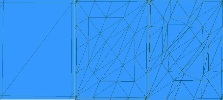
The first image is without tessellation.
The second is with all tessellation values = 4 and partitioning = fractional_even.
The third is the same tessellation values and partitioning = fractional_odd.
The fractional values apparently allow you to specify values that can slide from one integer value to the next, preventing popping artifacts in level of detail systems.
There’s not much to our second function. As mentioned above, we just pass through the position and normal for each control vertex of the patch.
The tessellation stage takes the information from the hull shader and spits out all of the triangles and vertices that we requested. In our case, a tessellation factor of 4 for each factor creates 24 new triangles.
The job of the domain shader is to set all of the values for the new vertices created, similar to what the vertex shader does, but for the new vertices.
The new vertices are defined in terms of their locations within the original patch, by (u, v) coordinates for a square and by (u, v, w) barycentric coordinates for a triangle. It is our job to interpolate from the original control points to these new points and output the correct position and normal.
cbuffer ConstantBuffer : register(b0)
{
	float4x4 viewproj;
	float4 eye;
	int height;
	int width;
}

struct DS_OUTPUT
{
	float4 pos : SV_POSITION;
	float4 norm : NORMAL;
};

// Output control point
struct HS_CONTROL_POINT_OUTPUT
{
	float4 pos : POSITION0;
	float4 norm : NORMAL;
};

// Output patch constant data.
struct HS_CONSTANT_DATA_OUTPUT
{
	float EdgeTessFactor[3]			: SV_TessFactor; // e.g. would be [4] for a quad domain
	float InsideTessFactor			: SV_InsideTessFactor; // e.g. would be Inside[2] for a quad domain
};

#define NUM_CONTROL_POINTS 3

[domain("tri")]
DS_OUTPUT main(
	HS_CONSTANT_DATA_OUTPUT input,
	float3 domain : SV_DomainLocation,
	const OutputPatch<HS_CONTROL_POINT_OUTPUT, NUM_CONTROL_POINTS> patch)
{
	DS_OUTPUT output;

	output.pos = float4(patch[0].pos.xyz*domain.x+patch[1].pos.xyz*domain.y+patch[2].pos.xyz*domain.z,1);
	output.pos = mul(output.pos, viewproj);
	output.norm = float4(patch[0].norm.xyz*domain.x + patch[1].norm.xyz*domain.y + patch[2].norm.xyz*domain.z, 1);

	return output;
}
My first instinct was to continue to multiply the position of the original vertices by our view/projection matrix in the vertex shader. After all, when we’re interpolating, does it really matter whether the points are in world space or view/projection space? It’s still just interpolating between three points in space.
Apparently, it does. When I was transforming the vertices in the vertex shader and passing them to the tessellation pipeline, I was getting nothing out. Just a blank screen. It wasn’t until I moved the view/projection transform to the domain shader that I finally got my triangles back.
As I suspected back in Part 6, it is safe to do the normal calculation in the vertex shader and interpolate in the domain shader. Since we aren’t currently displacing the new vertices at all, this will still be an accurate normal. With our fill mode set to Solid instead of Wire frame, you cannot tell the difference in the images (other than the frame rate, which we’ll get to.).

A close-up look at part of our terrain, before and after tessellation.
Other than the change mentioned above with when we transform the vertices by the view/projection matrix, there is no difference in our vertex and pixel shaders, so we won’t bother looking at them.
Performance
At this point, we are now turning every triangle we sent to the GPU into 24 sub-triangles. For a 1024×1024 height map, this means we are sending about 2 million triangles to the GPU, and generating about 48 million new triangles.
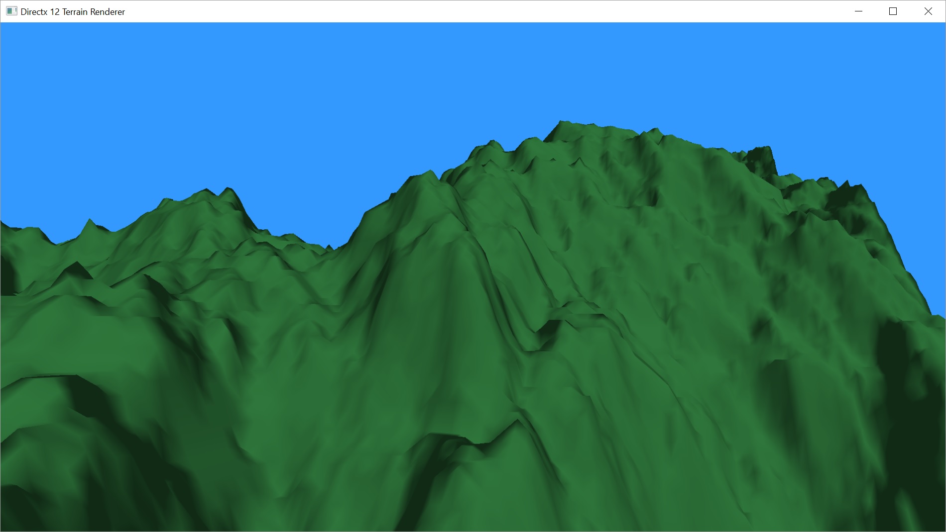
As you can probably imagine, that has had a pretty significant effect on our frame rate. For the above mentioned scene, rendered with Solid fill mode, each frame takes about 1.3ms to render, giving a frame rate of around 750fps, according to Visual Studio’s Graphics Debugger. The same scene rendered with tessellation enabled, looking exactly the same but with a lot more polygons, takes about 22.3ms to render, with a frame rate of about 45fps.
Here’s a screen shot where I stopped the camera to get those numbers.
As I mentioned back in the project introduction, I’m not super concerned with performance, but I was hoping to keep things rendering at a good clip. Minimum 60fps, preferably above 120fps. I haven’t added a level of detail system yet, but I also haven’t added shadows or a colour palette1.
Next up, we’re going to reduce the size of the initial mesh and use tessellation to add back the detail we lose. From there, we’ll add a simple dynamic Level-Of-Detail system and Frustum Culling to help speed things up and still give us the ability to add more close-up detail than we can get from the height map by itself. The next post or two should cover everything except the actual addition of high frequency detail. We’ll worry about that later.
Thanks for reading, and if you’d like the latest code, you can get it at GitHub. I post on a delay, so that code may actually include things I haven’t covered yet.
Traagen