The only thing left to do with shadows is to try to improve the frame rate. At the moment, we are rendering the entire terrain four times, once for each cascade. On top of that, we perform a fifth pass with view frustum culling for the final render. That’s a lot of geometry. We’ve already tuned our dynamic level of detail system to lighten the load a bit, but it would make sense to try and perform frustum culling for the shadow cascades as well.
There’s a really cool method for getting a tight frustum for this culling. L Spiro describes it pretty thoroughly here. But I already have an implementation to get the six plane frustum from the view/projection matrix and code to perform frustum culling based on that. It will only take a few minutes to get that up and running. If it gets me all the performance I need, why bother with a more complicated algorithm?
We already went over the code for this in Part 10, and I don’t want to repeat myself, so let’s just quickly look at one point.
Because we are using PCF and also moving our shadows in texel-sized increments, we needed to add a rounding matrix to our view/projection matrix. I originally linked to a good explanation of that in Part 15. We need to calculate our Shadow Frustum for each cascade after multiplying this rounding matrix into our view/projection matrix.
Once we’ve calculated the frustums for each cascade, it’s just a matter of passing that data to the shader as one of our shadow constants and adding the same frustum culling code we used in Part 10.
The end result wasn’t very impressive, I’m afraid. Last post, I said we were getting about 9.3ms frame rates on our 2048×2048 height map. Now that’s about 9.0ms. So we shaved a mere 0.3ms off our peak frame rate by adding frustum culling to our shadows. Not good.
But we can actually possibly do slightly better. We’re currently testing against all six planes of our shadow frustums, just like we did for our view frustum, but we know that the way our shadow frustums are defined, the near and far planes aren’t actually resulting in any culling. They are defined such that the entire terrain would be between them. So let’s remove those two planes from our culling. That will effectively eliminate 8 (2 planes * 4 cascades) plane tests per vertex of our initial mesh.
That shaved about another 0.3ms off of our frame rate, bringing us to the 8.7ms mark. Still too slow. L Spiro’s method would require quite a few more planes (she indicates up to 13 in her tutorial). Would the tighter culling reduce the overall geometry enough to warrant the additional plane tests? At this point, I’m trying not to have to find out.
Can we optimize this a little further? Maybe. Technically, our fourth and final cascade renders all geometry in the terrain. My reasoning for this was that our frustum radii had gotten so big by that point, the entire terrain would likely be inside anyway and this way we might get better resolution. But it means there is no point performing frustum culling on the fourth pass. If we could tell the GPU to skip it, we’d shave another 4 plane tests per vertex off. Not much, but worth a shot.
This didn’t really help. Given a margin for error on what my peak frame rate actually is, testing for which cascade we’re dealing with did not improve our frame rate at all. And if it did, it was only by about 0.1ms. It is effectively worthless to have another branch to test for the last cascade.
So what if I change my last cascade so it actually has a smaller size that may result in some culling? Well, that introduced some issues that I’d have to look at fixing where parts of distant terrain may not be getting shadowed at all. If I made the far plane of that final cascade big enough to catch that terrain, then I’m back to where I was. And having that shorter far plane didn’t affect the frame rate. Or rather, it actually increased the frame rate to 8.8ms, but I just got finished saying 0.1ms is within a reasonable margin for error on how I’m getting my frame rates.
As a final attempt at improving the frame rate, I decided to see what sort of effect changing the levels of tessellation in the shadow maps would have. In Part 15, I talked about this. I saved a huge amount of performance by reducing the maximum tessellation for the shadow passes from 64 to 16. So I tried reducing it further to 4. That basically brings us back to the original resolution of our height map. It still linearly falls off to zero tessellation as previously. This got me an improvement to 7.2ms, which puts me just over the 120fps mark, around 137fps, that I was hoping to maintain. But I can tell the difference in some areas. It isn’t a huge deal. If I didn’t have further plans, I’d be perfectly happy with the results.
But my next step after this is going to be to add a displacement map to offset all the added detail. I think reducing the tessellation for the shadows so much will have a noticeable impact on quality at that point. For now, I’m going to leave the tessellation as it originally was in Part 15. Once I have the displacement mapping in place, I’ll look at adjusting those values.
Perhaps I can set the tessellation based on the cascade. After all, there is significant overlap between the cascades and we only need objects to be tessellated significantly for the closest cascade.
At this point, I’m also not going to pursue trying to tighten up the frustum culling with the technique L Spiro describes. I am quite certain that the bottle neck in my current implementation is the shear amount of geometry. And much of that geometry is so far from the camera that it could be much lower resolution. If I move away from the static mesh and implement something like geometry clip mapping I can likely improve the frame rate significantly across all sizes of height maps. I don’t intend to do so for this project, but I do intend to add that as a future project.
Another option I may decide on later would be to reduce the resolution of the initial mesh. I currently use a tessFactor of 4, meaning that there is one vertex for every four texels of our height map. With a LOD tessellation factor of 64, this means our near geometry has a detail size of 100/16 = 6.25cm, assuming 1:1 tessellation would be one vertex per meter. If I change to an initial tessFactor of 8, my near geometry detail size goes to 100/8 = 12.5cm. That’s still pretty decent, but I may feel it isn’t enough for me. The same 2048×2048 height map would be able to render in less than 3ms at that level of detail, though. In fact, making that change would have our 4096×4096 height map capable of rendering at 7.2ms, 137fps. So, definitely a reduction in overall detail that I am considering.
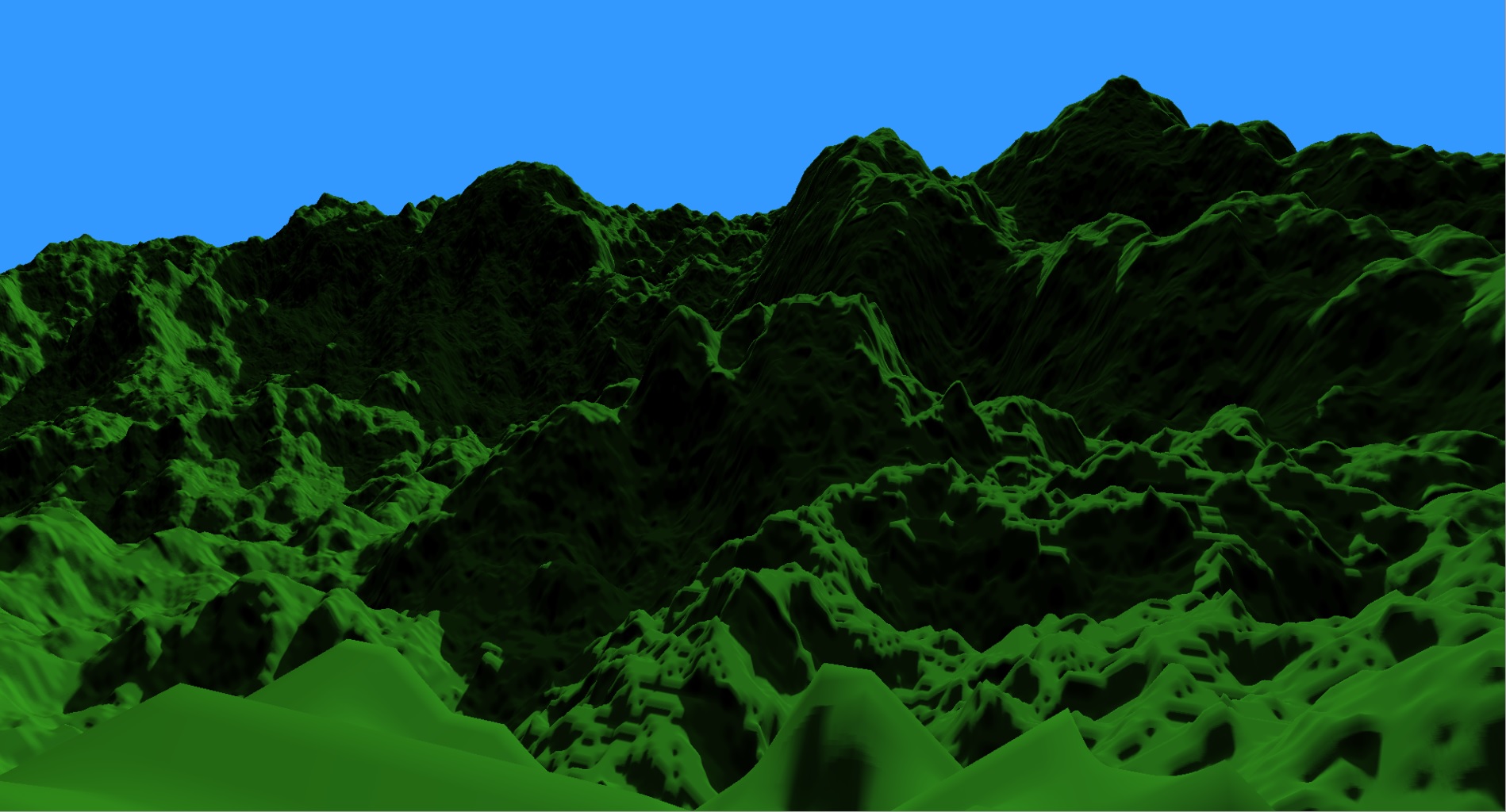
So for next post, we’re moving on from shadows. We did what we could and we’ll live with what we’ve got. They look pretty decent and seem mostly stable. They could be a tad faster, but that’s mostly a problem with the amount of geometry. Next post, we’ll look at adding detail by displacing the existing geometry. After that, we’ll look at adding a detail layer with normal/bump mapping.
For the latest code, go to GitHub.
Traagen