We are finally moving on from shadows. I get to work on and talk about something else! The funny thing is that I actually implemented the stuff we’re going to talk about today prior to working on shadows, but I commented the code out and didn’t write a post on it then. I thought it made more sense to deal with this after shadows.
So today we talk about Normal mapping and Displacement mapping. I came to learn these techniques in a backwards sort of way. Most people learn Normal or Bump mapping first as a way of adding detail to textured surfaces. Displacement mapping is an evolution of this where you actually have small enough geometry that you can displace the vertices to add the same detail in a more real way.
We’ve already figured out Displacement mapping, though. That is exactly how we generate our terrain. We create new geometry and we displace the vertices. Adding additional detail is simple. Just look up a height value in a displacement map and add that to the displacement we’re already creating. To make things more interesting, we can also calculate the normal of the vertex before adding the additional detail displacement, and then displace the vertex along that normal.
// in Domain Shader
...
float3 norm = estimateNormal(output.tex);
float disp = 2.0f * displacementmap.SampleLevel(displacementsampler, output.tex * 64.0f, 0.0f).w - 1.0f;
output.worldpos += norm * disp;
...
You probably noticed the hard-coded value 64 getting multiplied to the texture coordinates. That’s so we can use the same texture coordinates that stretches the height map over the terrain. Now we are essentially tiling our displacement map 64×64 times.
Of course, if you displace along the normal, then how do you calculate the new normal of the vertex? If you’re just displacing vertically, you’re not adding any really interesting detail, but calculating the normal is easy. I looked back and realized I haven’t really gone over the normal calculation in a while. The last time I talked about normals was way back in Part 6, and at that point I was still calculating them in the Vertex Shader. We’ve long since moved to calculating them in the Domain and Pixel Shaders.
Here’s the function we use to get the normal based on the initial height map.
float3 estimateNormal(float2 texcoord) {
	float2 b = texcoord + float2(0.0f, -0.3f / depth);
	float2 c = texcoord + float2(0.3f / width, -0.3f / depth);
	float2 d = texcoord + float2(0.3f / width, 0.0f);
	float2 e = texcoord + float2(0.3f / width, 0.3f / depth);
	float2 f = texcoord + float2(0.0f, 0.3f / depth);
	float2 g = texcoord + float2(-0.3f / width, 0.3f / depth);
	float2 h = texcoord + float2(-0.3f / width, 0.0f);
	float2 i = texcoord + float2(-0.3f / width, -0.3f / depth);

	float zb = heightmap.SampleLevel(hmsampler, b, 0) * scale;
	float zc = heightmap.SampleLevel(hmsampler, c, 0) * scale;
	float zd = heightmap.SampleLevel(hmsampler, d, 0) * scale;
	float ze = heightmap.SampleLevel(hmsampler, e, 0) * scale;
	float zf = heightmap.SampleLevel(hmsampler, f, 0) * scale;
	float zg = heightmap.SampleLevel(hmsampler, g, 0) * scale;
	float zh = heightmap.SampleLevel(hmsampler, h, 0) * scale;
	float zi = heightmap.SampleLevel(hmsampler, i, 0) * scale;

	float x = zg + 2 * zh + zi - zc - 2 * zd - ze;
	float y = 2 * zb + zc + zi - ze - 2 * zf - zg;
	float z = 8.0f;

	return normalize(float3(x, y, z));
}
You may remember from Part 6 that I talked about using 4, 6, or 8 neighbours to calculate the normal. We’re now using 8. There isn’t a noticeable difference in performance and I have found that I get fewer cases where the normals look wrong.
Also, even though I’m calculating the normal in the Domain Shader, I don’t pass it to the Pixel Shader. Instead, I recalculate it in the Pixel Shader. I find I get less swimming as we move about the terrain this way and it doesn’t significantly impact performance. Maybe 0.1ms or 0.2ms.
If we wanted to add a further displacement along the vertical, we’d just sample the displacement map and add directly to the height map samples zb to zi. No problem.
If we want to displace along the normal, however, now we run into a problem. How to calculate the new normal now? We’d have to sample the height map enough times to build the initial normal for each of the neighbours, displace them all, and then calculate the new normal for the point we’re working on. That’s around 70 texture samples per vertex/pixel. Not going to happen.
Here’s where Normal mapping comes to the rescue. Normal mapping works by working in the plane of the surface. Calculate the normal of the displacement/normal map as if the surface is pointing straight up, then transform that normal into world space.
To do this, I found a method presented by Christian Shuler that calculates tangent and cotangent vectors1 in the Pixel Shader.
float3x3 cotangent_frame(float3 N, float3 p, float2 uv) {
	// get edge vectors of the pixel triangle
	float3 dp1 = ddx(p);
	float3 dp2 = ddy(p);
	float2 duv1 = ddx(uv);
	float2 duv2 = ddy(uv);

	// solve the linear system
	float3 dp2perp = cross(dp2, N);
	float3 dp1perp = cross(N, dp1);
	float3 T = dp2perp * duv1.x + dp1perp * duv2.x;
	float3 B = dp2perp * duv1.y + dp1perp * duv2.y;

	// construct a scale-invariant frame
	float invmax = rsqrt(max(dot(T, T), dot(B, B)));
	return float3x3(T * invmax, B * invmax, N);
}

float3 perturb_normal(float3 N, float3 V, float2 texcoord) {
	// assume N, the interpolated vertex normal and
	// V, the view vector (vertex to eye)
	float3 map = 2.0f * displacementmap.Sample(displacementsampler, texcoord).xyz - 1.0f;
	float3x3 TBN = cotangent_frame(N, -V, texcoord);
	return normalize(mul(map, TBN));
}

float4 main(DS_OUTPUT input) : SV_TARGET
{
	float3 norm = estimateNormal(input.tex);
	float3 viewvector = eye.xyz - input.worldpos;
	norm = perturb_normal(norm, viewvector, input.tex * 64.0f);

	float4 color = float4(0.22f, 0.72f, 0.31f, 1.0f);

	float shadowfactor = decideOnCascade(input.shadowpos);
	float4 diffuse = max(shadowfactor, light.amb) * light.dif * dot(-light.dir, norm);
	float3 V = reflect(light.dir, norm);
	float3 toEye = normalize(eye.xyz - input.worldpos);
	float4 specular = shadowfactor * 0.1f * light.spec * pow(max(dot(V, toEye), 0.0f), 2.0f);

	return (diffuse + specular) * color;
}
You probably noticed that in my Domain Shader I sample the w channel of the displacement map and in the Pixel Shader, it’s the xyz channels. My displacement map is actually two files that I load and combine into one four channel texture. The height map is stored in the w channel and the normal map is stored in the xyz channels.
Here’s the two maps separately:
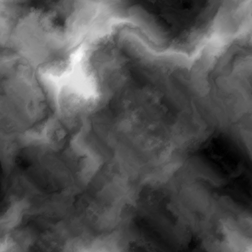
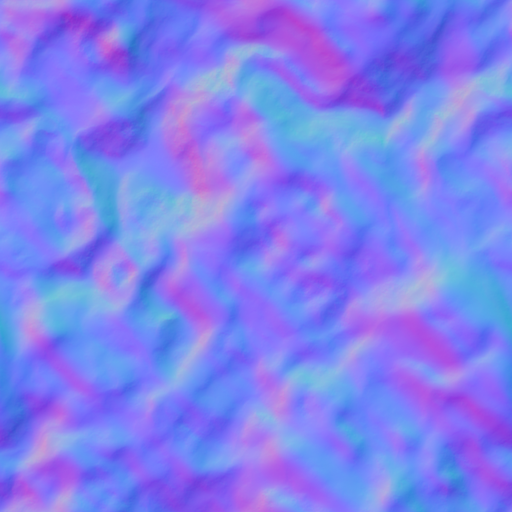
This just prevents me from having to calculate the normals on the fly from the height map.
I downloaded the height map from a random site found from a Google search, like all my height maps thus far. The normal map was generated from the height map using a tool you can get on Steam called Mindtex 2. I think I got it on sale at some point. I’ve actually found it pretty handy for this sort of thing.
This method of calculating the normals didn’t work for me with the terrain’s primary height map. The problem being that the normals created are based on the height values being between 0 and 1. If you change the scale, as I do for the height map, it changes the normals. I don’t have any pictures, but I found the lighting just didn’t work when I tried to scale the normals to match the terrain. If I can figure that out, I may switch.
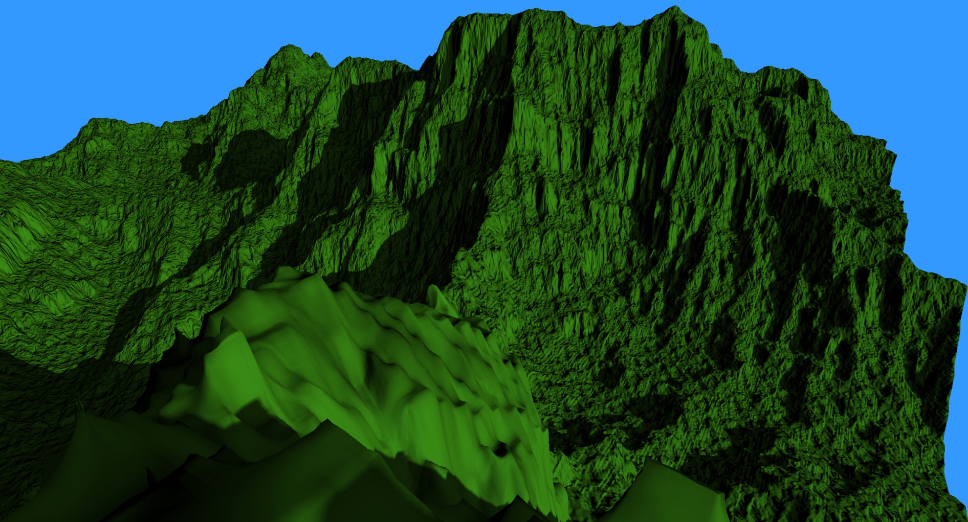
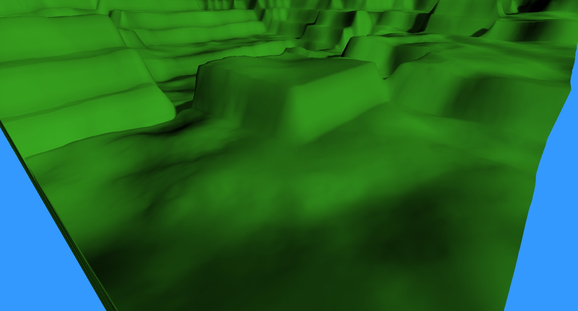
For now, I’m using the displacement map at the unit scale, so I don’t need to worry about this scaling issue. Let’s take a look at what the terrain looks like with the Displacement and Normal mapping enabled.

If you remember from last post, I mentioned that I was considering reducing the tessFactor from 4 to 8, but I wasn’t sure what impact that would have on the detail provided by Displacement mapping. That image has a tessFactor of 4. Let’s check out an image from the same view point, but with a tessFactor of 8.

I can’t even tell the difference. Well, I guess that means I’m going to reduce the tessFactor! Yay frame rates!
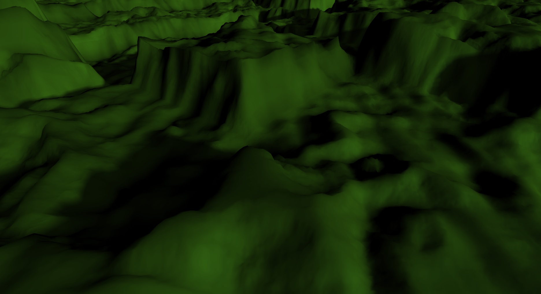
Just for the hell of it, let’s compare those images with one before displacement mapping.
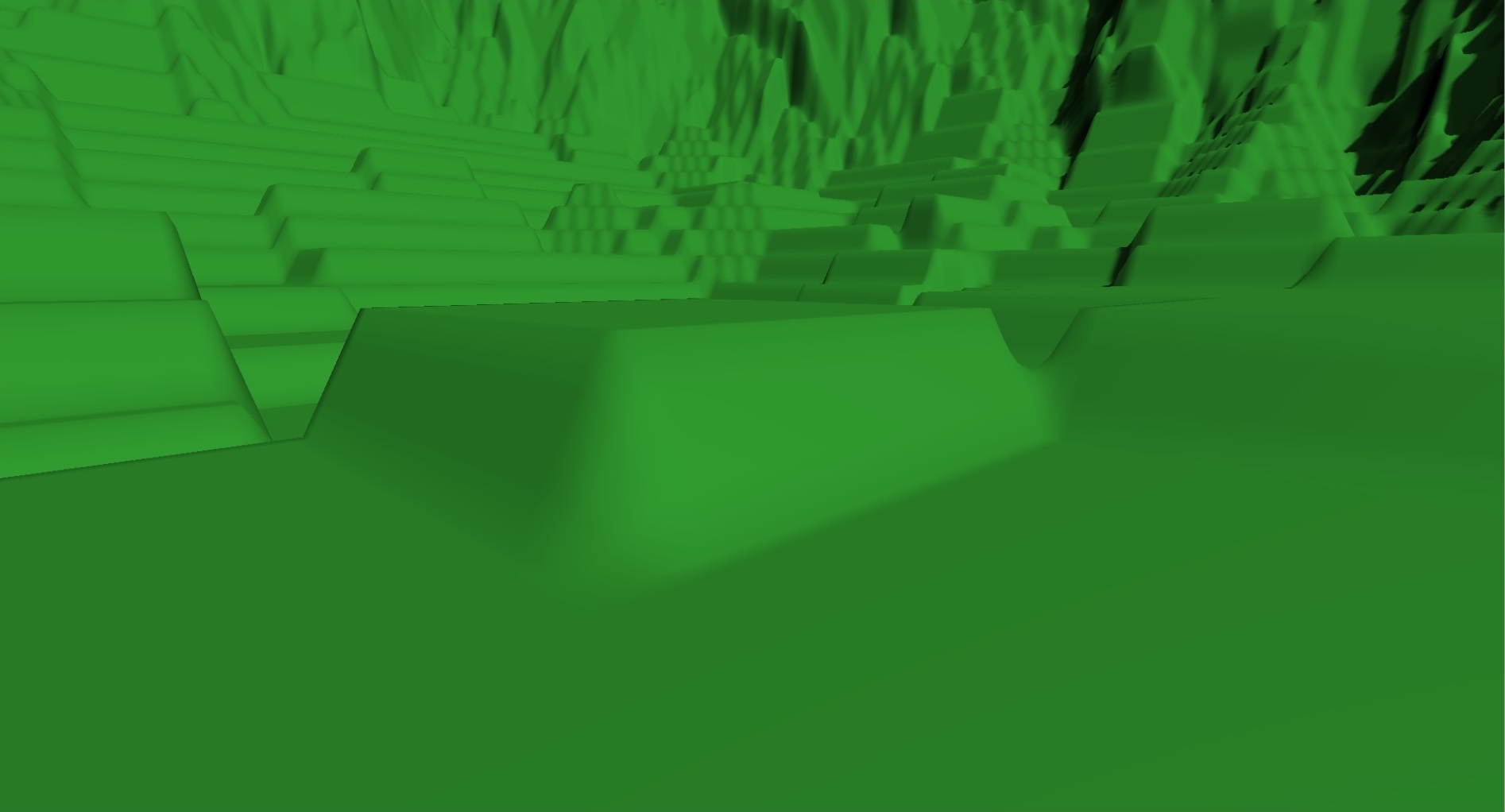
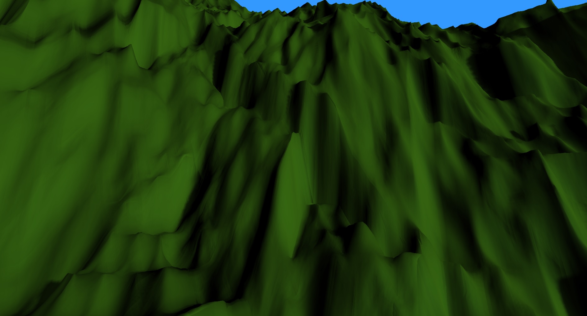
Quite the difference. Considering the height values in the displacement map are all between 0 and 1, we’re getting a huge amount of displacement. I like it, but I’ll have to decide if I want that much or if I want to figure out proper scaling to shrink it down a bit. It would also change quite a bit if I change that value I used to set how much it tiles. Here it is at 128:
And here it is at 32:
One thing I haven’t dealt with yet is the stretching that happens when you look at a vertical surface.
With Displacement mapping, it isn’t that big a deal. It kind of looks like you don’t get as much detail. With straight normal mapping, and with other forms of texture mapping, it can look a lot worse because the texture is literally being stretched.
We’re taking a flat texture and fitting it to a surface which is very much not flat, but our texture coordinates for the surface assume that it is. This causes the texture to look pretty good on relatively horizontal regions and terrible on vertical regions.
In the next post, I hope to look at adding tri-planar mapping to get around this issue.
Another issue I haven’t dealt with yet is our View Frustum Culling. The Displacement mapping changes the dimensions of each patch of terrain quite a bit. That changes the bounding box so now you can occasionally see patches getting culled that shouldn’t be. I’ll have to come up with a solution for that before too long.
I’m also hoping to have an additional detail map added. That map won’t be affecting the displacement of vertices. It will just add additional Normal mapping for more detail up close. My eventual goal is to have a different detail map based on the height and slope of the terrain. That may be a couple of posts away.
For the latest code, go to GitHub.
Traagen
Pingback: WebGPU for Metal Developers, Part Two – Metal by Example