Last post, we added displacement mapping and normal mapping to the terrain. This added a fair bit more detail, but sloped surfaces kind of looked stretched. It’s not the end of the world with displacement mapping, but I figured I should fix it before adding a detail map.
Triplanar mapping is a pretty common solution. The idea is pretty well explained online:
- This is the main tutorial I used.
- This has a slightly different method for setting the blend weights.
- This has yet another method for the blend weights.
The basic idea is that you sample your texture three times, once each using texture coordinates representing a surface aligned with the xy, xz, and yz planes. By then blending the three samples together based on the direction of the normal at the point, you get an approximate value that more or less eliminates the stretching caused by using a single plane on sloped surfaces like terrains. The first link above explains it pretty well. I’d read that.
The code is pretty straight forward. I’m sampling in both my Domain and Pixel Shaders, but I’ll just show the code for the Pixel Shader. Originally, sampling the displacement map looked like this:
float3 perturb_normal(float3 N, float3 V, float2 texcoord) {
	// assume N, the interpolated vertex normal and
	// V, the view vector (vertex to eye)
	float3 map = 2.0f * displacementmap.Sample(displacementsampler, texcoord.xy).xyz - 1.0f;
	float3x3 TBN = cotangent_frame(N, -V, texcoord.xy);
	return normalize(mul(map, TBN));
}
We’ve now replaced the line performing the sample with a new function call to a triplanar sampler:
float3 triplanar_sample(Texture2D tex, SamplerState sam, float3 texcoord, float3 N) {
	float3 blending = abs(N);
	// force weights to sum to 1.0
	blending = normalize(max(blending, 0.00001)); // force weights to sum to 1.0
	float b = blending.x + blending.y + blending.z;
	blending /= float3(b, b, b);

	float3 x = tex.Sample(sam, texcoord.yz).xyz;
	float3 y = tex.Sample(sam, texcoord.xz).xyz;
	float3 z = tex.Sample(sam, texcoord.xy).xyz;

	return x * blending.x + y * blending.y + z * blending.z;
}

float3 perturb_normal_triplanar(float3 N, float3 V, float3 texcoord, Texture2D tex, SamplerState sam) {
	float3 map = triplanar_sample(tex, sam, texcoord, N);
	map = map - 0.5f;

	float3x3 TBN = cotangent_frame(N, -V, texcoord);
	return normalize(mul(map, TBN));
}
Interestingly, all of the info I read about triplanar mapping indicates that it uses world coordinates as texture coordinates, meaning we can optimize our pipeline a bit by eliminating our texture coordinates. Not only did it save us a small amount of time and space, but it does actually look better when we sample using world position.
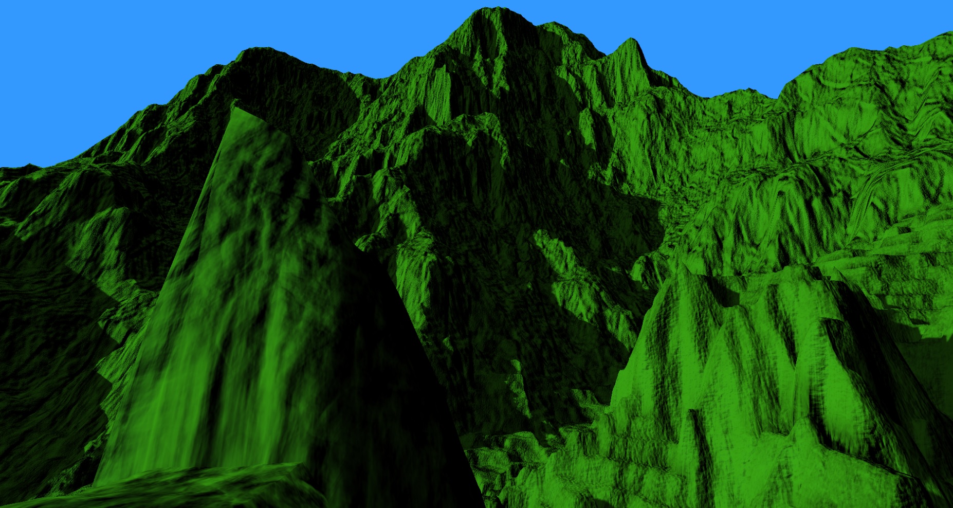
Here’s a before and after shot where we’ve enabled triplanar mapping for the displacement map. Triplanar mapping is done in both the Domain and Pixel shaders.
Original Single Lookup Displacement and Normal mapping.

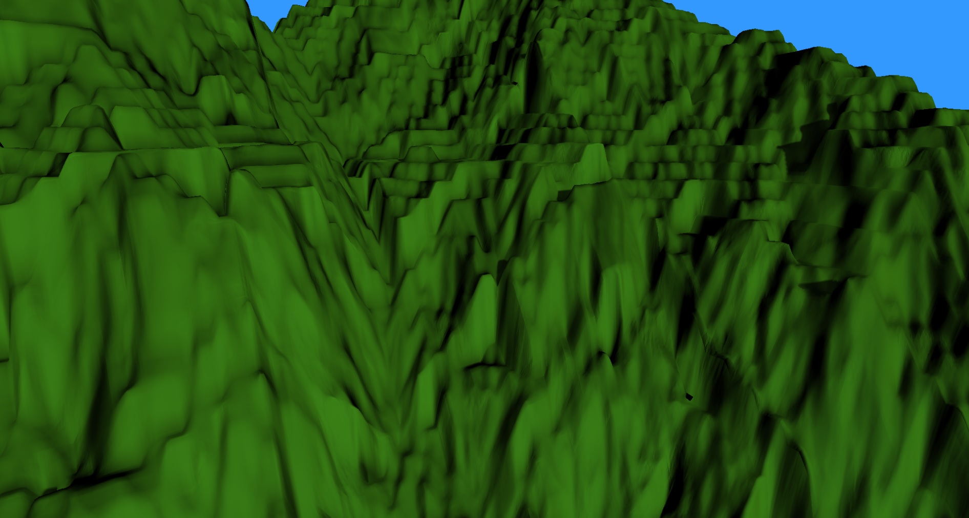
Triplanar Displacement and Normal mapping.
Sadly, the difference is actually pretty small. You can see a bit more detail, but not a lot.
I decided to move on to adding a detail map. The idea is to add an additional normal map that will be tiled at a higher frequency, resulting in a higher resolution. This will give us more detail up close. I used MindTex 2 to create a normal map from this rock texture:


The detail map is loaded exactly the same as our previous textures. It is only sampled in the Pixel Shader, so we can set shader visibility in our root signature to hopefully optimize access a bit.
// create a slot for the detail map.
rangesRoot[5].Init(D3D12_DESCRIPTOR_RANGE_TYPE_SRV, 1, 3);
paramsRoot[5].InitAsDescriptorTable(1, &rangesRoot[5], D3D12_SHADER_VISIBILITY_PIXEL);
To sample the shader, we use the same function we outlined above for the displacement map. All we have to do is pass it a different texture to sample.
In order to test the triplanar mapping with the detail map, I turned the displacement mapping off.
Here’s a before and after of a wall demonstrating the stretching of the normal map and how it looks after being fixed.

Vertical stretching

Less Stretching
Now let’s get a shot with both the displacement and detail maps:
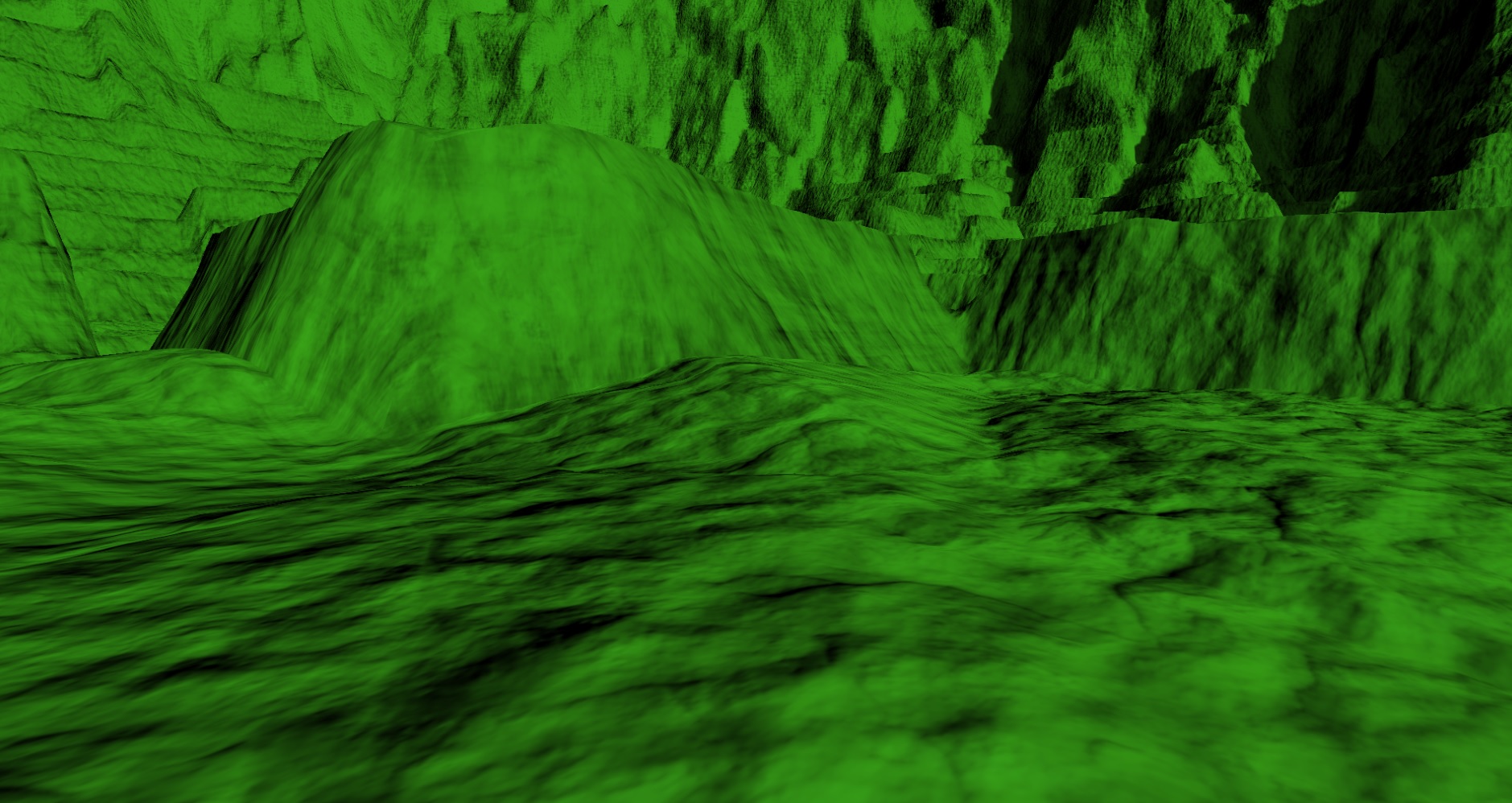
It was pretty disheartening to see how badly triplanar mapping hurts performance. The above image had the new method on for both the displacement map and detail map, and also in the shadow pass. The frame rate bottoms out at 16.9ms, 59fps. That misses our minimum performance goal of 60fps.
I found that I can turn off the triplanar mapping in the shadow pass without any noticeable difference. That saved us a whopping 0.5ms, getting us to 61.3fps.
I hadn’t seen a huge improvement in the looks of the terrain with triplanar mapping turned on for the displacement map, so I switched that back as well.
That actually helped a bit, getting our frame rate down to 13.1ms, 76fps.
There’s not a lot I can do to improve on this. Unfortunately, this likely means I’m going to miss that 60fps goal as I still want to add more texture mapping, to blend between different textures depending on the height and slope of the terrain. That’ll mean performing even more texture lookups. I may be able to minimize those, however. We’ll see.
Worse news! We’re no longer bottle necked by the geometry. All of this texture sampling, particularly in the Pixel Shader, has caused us to become fill rate bound. When I switch to a smaller height map, the frame rate does not improve. I appear to be reaching the limit of what my GPU can handle. We’ll push on and see how we wind up doing.
For the next post, my current plan is to fix my frustum culling. It’s hardly ever an issue, but occasionally I see patches popping because the bounding box of the patch does not take the displacement mapping into account.
For the latest code, visit GitHub.
Traagen