Well, I solved the problem with Shadow Mapping that I mentioned last post. Shadows now work. They’re not quite right, but they work. I’ll talk about the basic Shadow Mapping algorithm today and what’s wrong with my implementation currently. Hopefully I’ll be able to get the problems fixed over the weekend, then I can talk about those fixes next post.
Most of the work presented here is based heavily off of the chapter on Shadow Mapping in Introduction to 3D Game Programming with DirectX 12. I actually used the DirectX 11 version for most of it, but, as I mentioned last week, I wound up buying the new version when I was stuck. The chapters are pretty much identical, other than the API-specific code. I also studied the Microsoft Sample code. The Mini Engine and Multi-threading projects both have code for Shadow Maps.
The Algorithm
Shadow Mapping works by rendering the scene from the point of view of your light source, saving the depth of each pixel, and then using the resulting map as a texture we can sample against on a second pass where we render the scene normally. If you have multiple light sources, you need a separate pass and resulting texture for each light source.
There are tons of tutorials out there for Shadow Mapping, so I don’t want to spend too much time on the algorithm itself. Let’s try and focus on the DirectX 12 implementation.
The first thing we know is that we need a separate rendering pass to create the Shadow Map. This means a new Root Signature and Pipeline State Object. There isn’t much that needs to change. I created both from scratch, but most of the examples I looked at actually try to reuse the same Root Signature and copy a lot of the PSO settings from the normal render pass. I could have done this as well and then just set any buffers I didn’t need to NULL. That would literally just be the new shadow map buffer. Everything else is needed.
As for what is different, there are a couple of tweaks to the PSO.
- As long as we’re not rendering anything transparent, we don’t need to load a pixel shader at all. The algorithm works by only filling the Depth Buffer, which happens in the Rasterizer stage before the pixel shader is called. From what I’ve read, GPUs are optimized for this sort of Depth Buffer only rendering, so let’s hope we don’t kill our frame rate!
- We need to turn off the render targets. Since we’re not loading a pixel shader, we’re not technically ‘rendering’ anything.
- I’ve seen many examples and tutorials mention that changing your Cull Mode to cull front facing polygons instead of back facing will help with some common issues with Shadow Maps, like shadow acne, so I changed this variable.
- Related to the shadow acne issue, there are also values for DepthBias, DepthBiasClamp, and SlopeScaledDepthBias. These values allow you to add a bias to the vertex locations when you’re building your Shadow Map. The idea is that this limits shadow acne by repositioning vertices such that they don’t get missed because of the resolution of the Shadow Map. You can read what Microsoft has to say about Depth Bias. I had a hard time finding much about this, in terms of what values to use. Microsoft’s examples used -100, 0, and -1.5 respectively. In the DirectX 12 book I linked to previously, they use 100000, 0, and 1. Both sets of values either didn’t work at all or didn’t improve anything in my case. I’m currently using 100, 0, and 1.5 because at least the shadows work, even if they aren’t quite right yet.
- I could create a new constant buffer for the shadow map pass. It would be pretty much identical, but I would store a different value in the view/projection matrix slot. I could then use the same domain shader and just bind the new buffer.
- I could add a variable to the existing constant buffer for the light’s view/projection matrix and create a new domain shader that multiplies by that variable instead of the regular view/projection matrix.
mpGFX->CompileShader(L"RenderTerrainTessVS.hlsl", bcVS, VERTEX_SHADER);
mpGFX->CompileShader(L"RenderShadowMapHS.hlsl", bcHS, HULL_SHADER);
mpGFX->CompileShader(L"RenderShadowMapDS.hlsl", bcDS, DOMAIN_SHADER);

DXGI_SAMPLE_DESC descSample = {};
descSample.Count = 1; // turns multi-sampling off. Not supported feature for my card.

// create the pipeline state object
// create input layout.
D3D12_INPUT_LAYOUT_DESC	descInputLayout = {};
D3D12_INPUT_ELEMENT_DESC descElementLayout[] = {
	{ "POSITION", 0, DXGI_FORMAT_R32G32B32_FLOAT, 0, 0, D3D12_INPUT_CLASSIFICATION_PER_VERTEX_DATA, 0 },
	{ "POSITION", 1, DXGI_FORMAT_R32G32_FLOAT, 0, D3D12_APPEND_ALIGNED_ELEMENT, D3D12_INPUT_CLASSIFICATION_PER_VERTEX_DATA, 0 },
	{ "TEXCOORD", 0, DXGI_FORMAT_R32G32_FLOAT, 0, D3D12_APPEND_ALIGNED_ELEMENT, D3D12_INPUT_CLASSIFICATION_PER_VERTEX_DATA, 0 },
};

descInputLayout.NumElements = sizeof(descElementLayout) / sizeof(D3D12_INPUT_ELEMENT_DESC);
descInputLayout.pInputElementDescs = descElementLayout;

D3D12_GRAPHICS_PIPELINE_STATE_DESC descPSO = {};
descPSO.pRootSignature = sigRoot;
descPSO.InputLayout = descInputLayout;
descPSO.VS = bcVS;
descPSO.HS = bcHS;
descPSO.DS = bcDS;
descPSO.PrimitiveTopologyType = D3D12_PRIMITIVE_TOPOLOGY_TYPE_PATCH;
descPSO.RTVFormats[0] = DXGI_FORMAT_UNKNOWN;
descPSO.NumRenderTargets = 0;
descPSO.DSVFormat = DXGI_FORMAT_D24_UNORM_S8_UINT;
descPSO.SampleDesc = descSample;
descPSO.SampleMask = UINT_MAX;
descPSO.RasterizerState = CD3DX12_RASTERIZER_DESC(D3D12_DEFAULT);
descPSO.RasterizerState.CullMode = D3D12_CULL_MODE_FRONT;
descPSO.RasterizerState.FillMode = D3D12_FILL_MODE_SOLID;
descPSO.RasterizerState.DepthBias = 100;
descPSO.RasterizerState.DepthBiasClamp = 0.0f;
descPSO.RasterizerState.SlopeScaledDepthBias = 1.5f;
descPSO.BlendState = CD3DX12_BLEND_DESC(D3D12_DEFAULT);
descPSO.DepthStencilState = CD3DX12_DEPTH_STENCIL_DESC(D3D12_DEFAULT);
As far as what shaders I’m compiling, I use the exact same vertex shader as it is just a pass through. I could have used the same hull shader, but I decided to make a separate one that doesn’t do frustum culling, as our entire scene has to be in the frustum of the light at all times anyway. This may change later when I start working on Cascaded Shadow Maps.
My domain shader is nearly identical, but I need to multiply my vertex positions by a different view/projection matrix. I could handle this in two ways.
Obviously the first is the option that makes more sense, but I went with the second because I just didn’t get it at the time. This actually wound up being the source of all my troubles getting Shadow Mapping working. Mostly. I actually thought I could just use the existing view/projection matrix slot for the light in the shadow pass and then update it to the camera for the normal pass. The problem with this is that both passes are using the same buffer in video memory, not separate copies like I assumed. So I was overwriting the value before the shadow pass had a chance to use it.
I finally figured that out because when I went into the graphics analyzer in Visual Studio and captured a set of frames, it would slow the frame rate down enough that the shadows would actually show up! Talk about confusing. So rather than make an entirely new buffer, I just quickly added a variable to the existing one and made a copy of the domain shader that used that variable.
I’m definitely going to go back and fix this. It’s an ugly way of doing it, and possibly less efficient, as well.
It took me a while to figure out what format to use for the depth stencil buffer. The depth buffer literally is the shadow map. We create a buffer for it, like a normal depth buffer. That basically means that we create a default buffer but no upload buffer. Then we make a Depth Stencil View and a Shader Resource View for it.
// Create the shadow map texture buffer.
D3D12_RESOURCE_DESC	descTex = {};
descTex.Alignment = 0;
descTex.MipLevels = 1;
descTex.Format = DXGI_FORMAT_R24G8_TYPELESS;
descTex.Width = width;
descTex.Height = height;
descTex.Flags = D3D12_RESOURCE_FLAG_ALLOW_DEPTH_STENCIL;
descTex.DepthOrArraySize = 1;
descTex.SampleDesc.Count = 1;
descTex.SampleDesc.Quality = 0;
descTex.Dimension = D3D12_RESOURCE_DIMENSION_TEXTURE2D;
descTex.Layout = D3D12_TEXTURE_LAYOUT_UNKNOWN;

D3D12_CLEAR_VALUE clearValue;	// Performance tip: Tell the runtime at resource creation the desired clear value. (per microsoft examples)
clearValue.Format = DXGI_FORMAT_D24_UNORM_S8_UINT;
clearValue.DepthStencil.Depth = 1.0f;
clearValue.DepthStencil.Stencil = 0;

mpGFX->CreateCommittedResource(mpShadowMap, &descTex, &CD3DX12_HEAP_PROPERTIES(D3D12_HEAP_TYPE_DEFAULT), D3D12_HEAP_FLAG_NONE, D3D12_RESOURCE_STATE_PIXEL_SHADER_RESOURCE, &clearValue);
mpShadowMap->SetName(L"Shadow Map Texture Buffer");

D3D12_DEPTH_STENCIL_VIEW_DESC descDSV = {};
descDSV.Format = DXGI_FORMAT_D24_UNORM_S8_UINT;
descDSV.ViewDimension = D3D12_DSV_DIMENSION_TEXTURE2D;
descDSV.Texture2D.MipSlice = 0;
descDSV.Flags = D3D12_DSV_FLAG_NONE;

mpGFX->CreateDSV(mpShadowMap, &descDSV, mlDescriptorHeaps[1]->GetCPUDescriptorHandleForHeapStart());

// Create the SRV for the heightmap texture and save to Terrain object.
D3D12_SHADER_RESOURCE_VIEW_DESC	descSRV = {};
descSRV.Shader4ComponentMapping = D3D12_DEFAULT_SHADER_4_COMPONENT_MAPPING;
descSRV.Format = DXGI_FORMAT_R24_UNORM_X8_TYPELESS;
descSRV.ViewDimension = D3D12_SRV_DIMENSION_TEXTURE2D;
descSRV.Texture2D.MipLevels = descTex.MipLevels;
descSRV.Texture2D.MostDetailedMip = 0;
descSRV.Texture2D.ResourceMinLODClamp = 0.0f;
descSRV.Texture2D.PlaneSlice = 0;

CD3DX12_CPU_DESCRIPTOR_HANDLE handleSRV(mlDescriptorHeaps[0]->GetCPUDescriptorHandleForHeapStart(), 3, msizeofCBVSRVDescHeapIncrement);
mpGFX->CreateSRV(mpShadowMap, &descSRV, handleSRV);
Every format I tried didn’t seem to be working. This was before I fixed the bug with the view/projection matrix, but I did get something different when I switched to the values above, which came from the DirectX 12 book. I’ll go back and try some of the other depth stencil related formats. They should all work, in theory. Some are just higher or lower precision. This one has memory for both a depth buffer and a stencil buffer, but we currently only use the depth portion (I think).
Since this is a different render pass, it probably has different dimensions than your default pass1, so we need to set up a viewport and scissor rectangle for this pass.
// create a viewport and scissor rectangle as the shadow map is likely of different dimensions than our normal view.
mShadowMapViewport.TopLeftX = 0;
mShadowMapViewport.TopLeftY = 0;
mShadowMapViewport.Width = (float)width;
mShadowMapViewport.Height = (float)height;
mShadowMapViewport.MinDepth = 0;
mShadowMapViewport.MaxDepth = 1;

mShadowMapScissorRect.left = 0;
mShadowMapScissorRect.top = 0;
mShadowMapScissorRect.right = width;
mShadowMapScissorRect.bottom = height;
Once we’ve set everything up, the render pass is pretty much the same as the normal pass. Set the render targets, clear the depth stencil view, set the root signature and PSO, set all of your resources, and draw the objects in the scene. We also need to set resource transition barriers for the shadow map buffer to ensure that it is configured for writing when we’re drawing to it, then switched to read before we tried to read from it.
cmdList->RSSetViewports(1, &mShadowMapViewport);
cmdList->RSSetScissorRects(1, &mShadowMapScissorRect);

cmdList->ResourceBarrier(1, &CD3DX12_RESOURCE_BARRIER::Transition(mpShadowMap, D3D12_RESOURCE_STATE_PIXEL_SHADER_RESOURCE, D3D12_RESOURCE_STATE_DEPTH_WRITE));

cmdList->ClearDepthStencilView(mlDescriptorHeaps[1]->GetCPUDescriptorHandleForHeapStart(), D3D12_CLEAR_FLAG_DEPTH, 1.0f, 0, 0, nullptr);
cmdList->OMSetRenderTargets(0, nullptr, false, &mlDescriptorHeaps[1]->GetCPUDescriptorHandleForHeapStart());
cmdList->SetPipelineState(mlPSOs[2]);
cmdList->SetGraphicsRootSignature(mlRootSigs[2]);

ID3D12DescriptorHeap* heaps[] = { mlDescriptorHeaps[0] };
cmdList->SetDescriptorHeaps(_countof(heaps), heaps);

// set the srv buffer.
CD3DX12_GPU_DESCRIPTOR_HANDLE handleSRV(mlDescriptorHeaps[0]->GetGPUDescriptorHandleForHeapStart(), 2, msizeofCBVSRVDescHeapIncrement);
cmdList->SetGraphicsRootDescriptorTable(0, handleSRV);

// set the per frame constant buffer.
XMFLOAT4 frustum[6];
C.GetViewFrustum(frustum);

PerFrameConstantBuffer constants;
float h = T.GetHeightMapDepth() / 2.0f;
float w = T.GetHeightMapWidth() / 2.0f;
constants.viewproj = C.GetViewProjectionMatrixTransposed();
constants.shadowviewproj = DNC.GetShadowViewProjectionMatrixTransposed(XMFLOAT3(w, h, 0.0f), sqrtf(w * w + h * h));
constants.eye = C.GetEyePosition();
constants.frustum[0] = frustum[0];
constants.frustum[1] = frustum[1];
constants.frustum[2] = frustum[2];
constants.frustum[3] = frustum[3];
constants.frustum[4] = frustum[4];
constants.frustum[5] = frustum[5];
constants.light = DNC.GetLight();
memcpy(mpPerFrameConstantsMapped, &constants, sizeof(PerFrameConstantBuffer));

cmdList->SetGraphicsRootDescriptorTable(1, mlDescriptorHeaps[0]->GetGPUDescriptorHandleForHeapStart());

// mDrawMode = 0/false for 2D rendering and 1/true for 3D rendering
T.Draw(cmdList, true);

cmdList->ResourceBarrier(1, &CD3DX12_RESOURCE_BARRIER::Transition(mpShadowMap, D3D12_RESOURCE_STATE_DEPTH_WRITE, D3D12_RESOURCE_STATE_PIXEL_SHADER_RESOURCE));
You’ll notice that I hard-coded a value there to pass to the GetShadowViewProjectionMatrixTransposed() method. That value describes a bounding sphere that contains the entire terrain. As you can see in the following image, there’s a lot of dead space around the terrain currently. We already have code to generate an Axis Aligned Bounding Box, so I’m going to try to rework the code in that method to use an AABB instead of the sphere.

This image was actually taken while the light was directly below the terrain. Because of Front-Face Culling, not much is visible from the top.
The GetShadowViewProjectionMatrixTransposed() method is very similar to the method we created for the camera way back in Part 4, only now we’re creating a matrix from the perspective of our Sun. Since the Sun is represented by a directional light, we’re going to base our view frustum off of the bounding sphere, so that the terrain is centered, and then we’ll use Orthographic projection so we don’t get any funky perspective warping in the shadows.
XMFLOAT4X4 DayNightCycle::GetShadowViewProjectionMatrixTransposed(XMFLOAT3 centerBoundingSphere, float radiusBoundingSphere) {
LightSource light = mdlSun.GetLight();
XMVECTOR lightdir = XMLoadFloat3(&light.direction);
XMVECTOR lightpos = -2.0f * radiusBoundingSphere * lightdir;
XMVECTOR targetpos = XMLoadFloat3(¢erBoundingSphere);
XMVECTOR up = XMVectorSet(0.0f, 1.0f, 0.0f, 0.0f);
XMMATRIX V = XMMatrixLookAtLH(lightpos, targetpos, up); // light space view matrix
// transform bounding sphere to light space
XMFLOAT3 spherecenterls;
XMStoreFloat3(&spherecenterls, XMVector3TransformCoord(targetpos, V));
// orthographic frustum
float l = spherecenterls.x - radiusBoundingSphere;
float b = spherecenterls.y - radiusBoundingSphere;
float n = spherecenterls.z - radiusBoundingSphere;
float r = spherecenterls.x + radiusBoundingSphere;
float t = spherecenterls.y + radiusBoundingSphere;
float f = spherecenterls.z + radiusBoundingSphere;
XMMATRIX P = XMMatrixOrthographicOffCenterLH(l, r, b, t, n, f);
XMMATRIX S = XMMatrixTranspose(V * P);
XMFLOAT4X4 final;
XMStoreFloat4x4(&final, S);
return final;
}
We also have a second, nearly identical method called GetShadowTransformMatrixTransposed(), which performs the same calculations, but adds a transformation to Texture space. This matrix is used in the normal draw pass to transform our vertices from world space to the shadow map’s texture space, so we can look up whether we’re in shadow. I’ll include just the extra code. A smarter implementation would create both matrices in one function that is run on update, and then we’d just have Get() methods. I’ll fix this soon.
// transform NDC space [-1, +1]^2 to texture space [0, 1]^2
XMMATRIX T(0.5f, 0.0f, 0.0f, 0.0f,
	0.0f, -0.5f, 0.0f, 0.0f,
	0.0f, 0.0f, 1.0f, 0.0f,
	0.5f, 0.5f, 0.0f, 1.0f);

XMMATRIX S = XMMatrixTranspose(V * P * T);
As I said above, there isn’t really any necessary change to the shaders. I made some because I did a pretty poor job on the implementation. Once I fix my code, I’ll probably be able to delete the extra shaders I added.
As for the final render pass, we add the new SRV we created for the Shadow Map and add the Transform matrix we made above. We also need to add a new sampler for the shadow map. Rather than just sampling the map, we want to do a comparison of the depth value stored against the depth value we calculate for the current point, which is found by multiplying the world position by the transform matrix. This step is done in the domain shader on the vertex level. We then pass it to the pixel shader as a texture coordinate that will be interpolated across the polygon. That multiplication and new output is the only thing new about our domain shader.
We do add a new function to our pixel shader. We are taking advantage of the fact that there is a built in function for doing Percentage Closer Filtering. The built in function automatically samples a 2×2 grid of the shadow map using the comparison sampler we just set up and linearly interpolates the results. Our function then takes a 3×3 grid of these samples and averages them. The idea here is to help with shadow acne, and to create softer shadows.
float calcShadowFactor(float4 shadowPosH) {
	// No need to divide shadowPosH.xyz by shadowPosH.w because we only have a directional light.

	// Depth in NDC space.
	float depth = shadowPosH.z;

	// Texel size.
	const float dx = SMAP_DX;

	float percentLit = 0.0f;
	const float2 offsets[9] = {
		float2(-dx,  -dx), float2(0.0f,  -dx), float2(dx,  -dx),
		float2(-dx, 0.0f), float2(0.0f, 0.0f), float2(dx, 0.0f),
		float2(-dx,   dx), float2(0.0f,   dx), float2(dx,   dx)
	};

	// 3x3 box filter pattern. Each sample does a 4-tap PCF.
	[unroll]
	for (int i = 0; i < 9; ++i) {
		percentLit += shadowmap.SampleCmpLevelZero(shadowsampler, shadowPosH.xy + offsets[i], depth);
	}

	// average the samples.
	return percentLit / 9.0f;
}
We can then multiply our diffuse and specular components by the shadow factor to add in the shadow component. I also added a quick check so that if the light is behind the point on the surface, we’d automatically put the point in shadow. I just added this because the Sun was lighting the terrain a bit after it had set.
return ambient + (diffuse + specular) * (dot(light.dir, norm) < 0 ? calcShadowFactor(input.shadowpos) : 0);
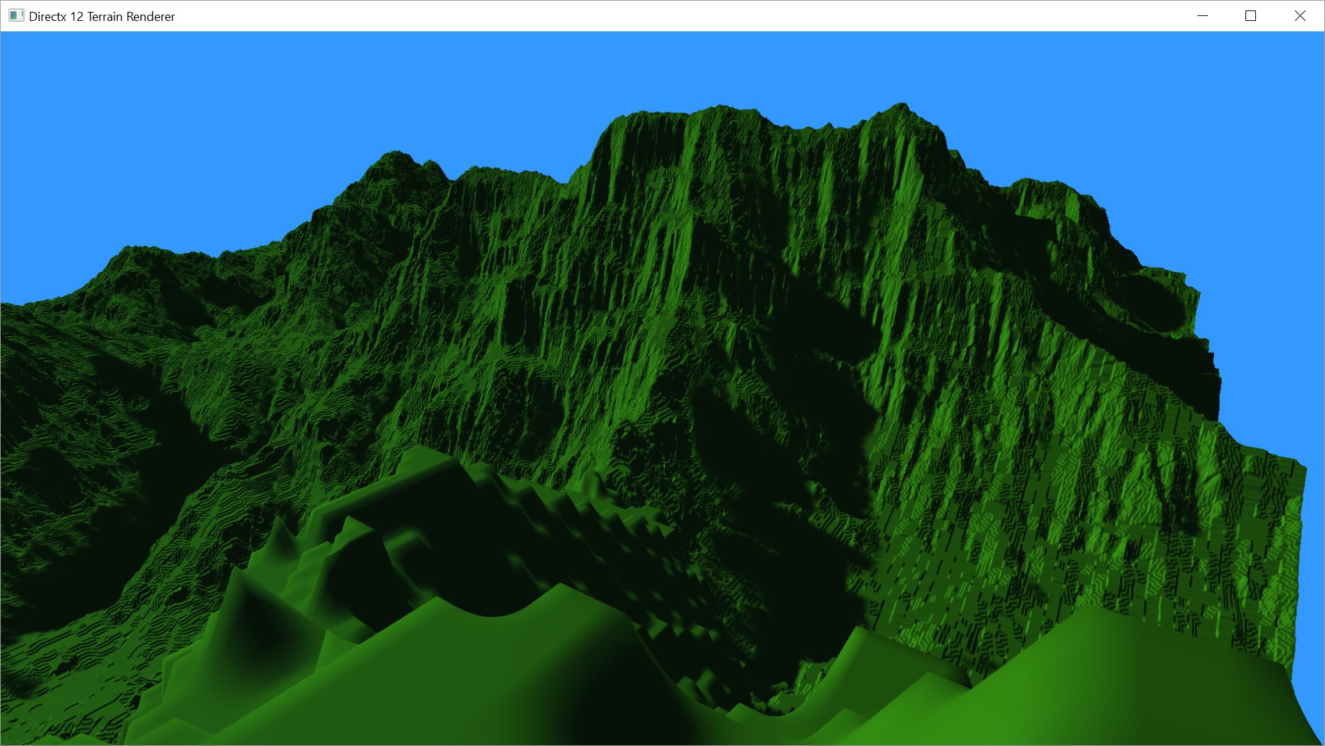
So that’s pretty much it for the basic Shadow Mapping algorithm. Things look pretty decent, at least from a distance.
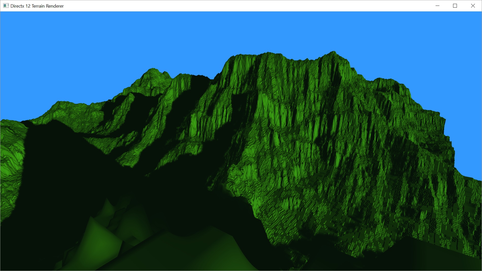
Problems
There are, however, a few problems. The first major one is how the shadows look up close.
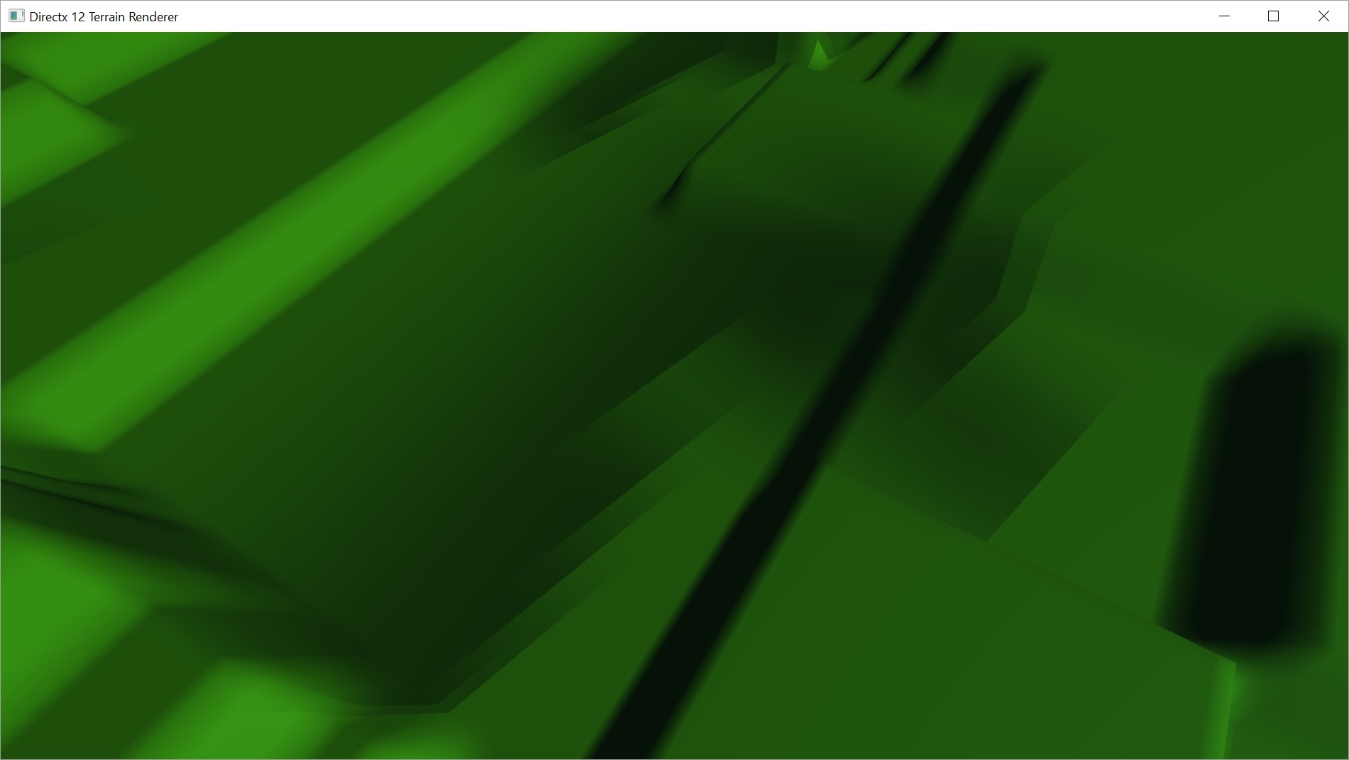
Pretty bad. First off, the shadow is too soft. You can barely even see it, but there is, in fact, a shadow cast across the flat area. You can see the jagged, badly aliased line across the ground where the shadow SHOULD be connected to the dark area, which is a steep wall. Pretty bad Peter Panning happening there. I played around a bit with the Depth Bias, but didn’t know what kinds of values to use to get rid of it. I also tried Normal Offset Bias, but didn’t have any better luck. I was pretty certain the problem here is that the resolution of the shadow map is just too low. Even a 4096×4096 shadow map, which is ridiculously big, only works out to 4 texels per 1m2 on the 2048×2048 height map in these pictures. The same size shadow map on a 512×512 height map actually works pretty well, but now the shadow map is 64 times the size of the height map. A 1024×1024 shadow map actually works fairly well, as well. Not quite as smooth, obviously. But better in terms of performance and memory.
There’s still an issue with areas within the shadow not being dark. I think it is also related to the resolution, but may not be completely that. The following video demonstrates this issue. In the second half of the clip, you’ll see the shadow sweep by. Once the umbra passes, part of the terrain will be slightly lit again until the Sun dips below even with the point. Given the Sun is behind something at this point, the region should be completely dark.
I was thinking these problems were all related to resolution, so I squeezed the light’s frustum down to a sphere of radius 100, compared to one of radius 1024 for the 2048×2048 heightmap or 256 for the 512×512 height map. I couldn’t see any issue at all within the area covered by that radius. The shadows looked perfect. Mind you, that was also a 4096×4096 shadow map. But if I implement Cascaded Shadow Maps and perhaps find some Depth Bias values that actually work, I think I can get these problems licked.
Those aren’t the only problems, though. I mentioned last post that my Sun rises and sets aligned with the Y axis. Since the terrain is also aligned with both the x and y axes, I should think the shadows would be aligned as well. You can see in the above video that they aren’t.
The following God’s eye view video shows the problem in a more pronounced way. It also appears that the problem is opposite at dawn and dusk.
I’m really not sure what’s causing this. I didn’t notice anything odd about the lighting without the shadows, so I’m fairly certain the Sun’s direction vector is updating correctly. I decided to render the shadow map directly as it is animating, so I can see what that is doing.
As I said before, there’s a lot of wasted space. Getting the light frustum tighter to the terrain would help with the resolution quite a bit.
I’m not sure why it rotates horizontally. I would have thought it would rotate vertically. I apparently have created a frustum with the light on its side…
…I stopped and fixed that as I was writing this post. I set the up vector to point along the y axis. I actually needed the cross product of that vector with the lightdir vector to get the correct up vector as the Sun direction rotates.
XMVECTOR up = XMVectorSet(0.0f, 1.0f, 0.0f, 0.0f);
up = XMVector3Cross(lightdir, up);
In that video above, it seemed to me as if the terrain is getting warped as it spins. I didn’t make a new video with it rotating vertically, but now it feels less like a warping and more like a wobble. I’ll have to work on getting that fixed this weekend.
Performance
Since there’s just a couple of (hopefully) minor non-performance-related issues to deal with, we may as well talk briefly about performance.
I was pretty disappointed. In Part 11, we were rendering our 2048×2048 height map at 3.8ms per frame, 266fps. Now? With a 4096×4096 shadow map, it took 10.4ms, 94fps. That’s a pretty big shadow map, so I tried a 1024×1024 one. Somehow it was slower, hitting 12.1ms, 82fps. A 512×512 shadow map was just as bad! Clearly, it isn’t the size of the map. It also doesn’t appear to be anything I’ve added to the regular render pass, so it must be the amount of geometry going through the shadow map pass.
We’re sending a mesh of vertices made up of 1 vertex per 4 texels of the height map. We then tessellate that based on the distance to the camera. We linearly interpolate from no tessellation at 512m to a tessellation factor of 64 up to 16m from the eye. You can check that out in Part 9. For the shadow map, I had read that you can sometimes cut down the tessellation factor without really hurting the scene. I tried changing the maximum tessellation factor in the shadow map to 8. It made a huge difference in the frame rate, getting us down below 5ms per frame, but it definitely impacted the quality of the shadows.
I decided to play a bit more with the tessellation factor. I discovered that in the normal render mode, I could tell no difference between a far distance of 512m, and 256m. That’s a lot of patches that don’t need to be tessellated at all. Plus, because we’re interpolating between near and far values, a shorter far distance means all the in between tessellation factors cover a shorter distance as well.
So switching both the shadow and normal render passes to use a closer far distance value looks exactly the same to me, but saves a ton of work. I was able to turn the shadow tessellation back up to max and still get a frame rate of 5.7ms, 175fps.
Hopefully I’ll have the basic Shadow Map implementation working much better by Tuesday. I don’t think I’ll get Cascaded Shadow Maps implemented by then, but we’ll see.
The latest code can be downloaded from GitHub.
Traagen