In order to create a height map texture on the GPU, we add a new task to our Terrain’s CreateDeviceDependentResources() method. While technically this task isn’t dependent on the previous tasks in the method, the code is set up to perform all of the tasks sequentially culminating in setting a boolean variable m_loadingComplete to indicate when we can start actually rendering. We’ll stick with this structure as it seems to work reasonably well and there is no reason at this stage for asynchronous execution.
task<void> createHeightmapTextureTask = createMeshTask.then([this]() {
	D3D11_TEXTURE2D_DESC descTex = { 0 };
	descTex.MipLevels = 1;
	descTex.ArraySize = 1;
	descTex.Width = m_wHeightmap * m_resHeightmap + 1;
	descTex.Height = m_hHeightmap * m_resHeightmap + 1;
	descTex.Format = DXGI_FORMAT_R32_FLOAT;
	descTex.SampleDesc.Count = 1;
	descTex.SampleDesc.Quality = 0;
	descTex.Usage = D3D11_USAGE_DYNAMIC;
	descTex.BindFlags = D3D11_BIND_SHADER_RESOURCE;
	descTex.CPUAccessFlags = D3D11_CPU_ACCESS_WRITE;

	D3D11_SUBRESOURCE_DATA dataTex = { 0 };
	dataTex.pSysMem = m_heightmap;
	dataTex.SysMemPitch = (m_wHeightmap * m_resHeightmap + 1) * sizeof(float);
	dataTex.SysMemSlicePitch = (m_hHeightmap * m_resHeightmap + 1) * (m_wHeightmap * m_resHeightmap + 1) * sizeof(float);
	DX::ThrowIfFailed(m_deviceResources->GetD3DDevice()->CreateTexture2D(&descTex, &dataTex, &m_hmTexture));

	D3D11_SHADER_RESOURCE_VIEW_DESC descSRV = {};
	descSRV.Texture2D.MipLevels = descTex.MipLevels;
	descSRV.Texture2D.MostDetailedMip = 0;
	descSRV.Format = descTex.Format;
	descSRV.ViewDimension = D3D11_SRV_DIMENSION_TEXTURE2D;
	DX::ThrowIfFailed(m_deviceResources->GetD3DDevice()->CreateShaderResourceView(m_hmTexture.Get(), &descSRV, &m_hmSRV));
});
This is a pretty typical texture creation. We set the format to a what we need, set the size based on the dimensions and resolution we’ve determined. The initialized height map data is passed in on creation.
Since my intention is to be iteratively generating the terrain and rendering each iteration, I need to be able to update the texture. Thus, I have set the CPUAccessFlags to write access and the Usage flags to Dynamic. Dynamic will allow us to map the texture to a CPU space and copy the updated height map over for each iteration.
Setting this code up made me realize a rather silly mistake I made in my height map declaration. If you refer to last post, I had declared my height map as a float** and initialized it dynamically as an array of arrays:
void Terrain::InitializeHeightmap() {
    unsigned int h = m_hHeightmap * m_resHeightmap + 1;
    unsigned int w = m_wHeightmap * m_resHeightmap + 1;
    m_heightmap = new float*[h];

    for (auto i = 0u; i < h; ++i) {
        m_heightmap[i] = new float[w];

        for (auto j = 0u; j < w; ++j) {
            m_heightmap[i][j] = 0.0f;
        }
    }
}
This does not necessarily create a contiguous block of memory for the entire two dimensional height map. Each array will be contiguous, but the arrays could all be stored in different blocks of memory. But when we pass this to DirectX, we need the data to be contiguous.
To fix this is pretty straight forward. We just change to a float*, a single array. Since our initialization is to 0, we hardly even need to change the code.
void Terrain::InitializeHeightmap() {
	unsigned int h = m_hHeightmap * m_resHeightmap + 1;
	unsigned int w = m_wHeightmap * m_resHeightmap + 1;
	m_heightmap = new float[h * w];

	for (auto i = 0u; i < h * w; ++i) {
		m_heightmap[i] = 0.0f;
	}
}
The only complication this change actually presents will be that we need to handle the calculation to find a specific (x, y) value ourselves. Once we assume an orientation, say Row Major order, then the formula can be intuited: index = y * width + x. For example, cell (10, 10) in a 101×101 height map would be heightmap[10 * 101 + 10] = heightmap[1020].
Now that we’ve created the Texture and a Shader Resource View for it on the GPU, we can attach it to our render pipeline. Unlike in DirectX 12, with DirectX 11 we bind shader resources to each shader that requires them, rather than to the pipeline in general.
// attach the heightmap
context->VSSetShaderResources(0, 1, m_hmSRV.GetAddressOf());
context->PSSetShaderResources(0, 1, m_hmSRV.GetAddressOf());
In our case, we’ll be accessing the height map from both the Vertex Shader and the Pixel Shader. We’ll access it in the Vertex Shader in order to displace our vertices to the correct height value. In the Pixel Shader, we’ll be calculating per pixel normals from the height values, just as in the Rendering Terrain project.
One last change is to update our Input Layout. The sample code had set each vertex to include a position and a colour. We don’t really need a per vertex colour going forward. For now, we can hard code a value. Eventually, we’ll add texturing in. But what we do need are texture coordinates for each vertex so we can determine which texel of our height map texture each vertex corresponds to. We update the code accordingly.
// in ShaderStructures.h
    struct Vertex { // used to be VertexPositionColor in the sample code.
        DirectX::XMFLOAT3 pos;
        DirectX::XMFLOAT2 uv;
    };

// in Terrain::CreateDeviceDependentResources()
constexpr std::array<D3D11_INPUT_ELEMENT_DESC, 2> vertexDesc = { {
	{ "POSITION", 0, DXGI_FORMAT_R32G32B32_FLOAT, 0,  0, D3D11_INPUT_PER_VERTEX_DATA, 0 },
	{ "TEXCOORD", 0, DXGI_FORMAT_R32G32_FLOAT, 0, 12, D3D11_INPUT_PER_VERTEX_DATA, 0 },
} };
Moving on to the shaders, it is interesting to note that the code we’re using takes into account whether the GPU supports the VPAndRTArrayIndexFromAnyShaderFeedingRasterizer option. That’s a mouthful, but basically it defines whether the GPU can access Viewport and Render Target information from any shader, or just the Geometry Shader.
If you’re not familiar with Geometry Shaders, one of the common uses is to set the SV_RenderTargetArrayIndex semantic to essentially stream geometry to a specific render target. For example, when rendering to a cube map in environment mapping. If your GPU supports setting the SV_RenderTargetArrayIndex semantic from other shaders, then you can leave out the Geometry shader entirely and set this in the Vertex shader, which will be faster. But an application would need to support both methods, so we have a VertexShader.hlsl and a VPRTVertexShader.hlsl, as well as a GeometryShader.hlsl. We determine how to set our pipeline up by calling the GetDeviceSupportsVprt() method of the provided DeviceResources class. If we didn’t have this ready-made class, we’d call the following to perform the check:
 // Check for device support for the optional feature that allows setting the render target array index from the vertex shader stage.
D3D11_FEATURE_DATA_D3D11_OPTIONS3 options;
m_d3dDevice->CheckFeatureSupport(D3D11_FEATURE_D3D11_OPTIONS3, &options, sizeof(options));
if (options.VPAndRTArrayIndexFromAnyShaderFeedingRasterizer) {
    m_supportsVprt = true; // or whatever we want to do.
}
But why do we need multiple render targets? Well, while it appears the HoloLens does not do Stereoscopic 3D like the Oculus Rift, it does have two lenses and the image needs to be sent to both. This is done by using instancing of the geometry.
context->DrawIndexedInstanced(m_indexCount, 2, 0, 0, 0);
The 2 in that call is the number of instances. Basically, we send the geometry to the GPU once, and tell it to make two copies. We can then direct it to treat each copy differently. For example, you could send the geometry for one tree to the GPU and tell it to draw that tree 1000 times in different locations and scales to create a forest by simply looking up a world matrix and scale factors in an array/buffer indexed by the instance id. In our case, we just use the instance id to determine which render target to send to.
It is probably slower to do so, but you could also duplicate the geometry in the Geometry Shader and send one set to each render target, as I talked briefly about here.
Let’s ignore the case where we need a Geometry Shader. The only thing it needs to do in our application is set the Render Target, so we’ll just look at the version of the Vertex Shader that does this.
// A constant buffer that stores the model transform.
cbuffer ModelConstantBuffer : register(b0)
{
    float4x4 model;
};

// A constant buffer that stores each set of view and projection matrices in column-major format.
cbuffer ViewProjectionConstantBuffer : register(b1)
{
    float4x4 viewProjection[2];
};

Texture2D<float> heightmap : register(t0);
SamplerState hmsampler : register(s0) {
	Filter = MIN_MAG_MIP_LINEAR;
};

// Per-vertex data used as input to the vertex shader.
struct VertexShaderInput
{
    min16float3 pos     : POSITION;
    min16float2 uv		: TEXCOORD0;
    uint        instId  : SV_InstanceID;
};

// Per-vertex data passed to the geometry shader.
// Note that the render target array index is set here in the vertex shader.
struct VertexShaderOutput
{
    min16float4 pos     : SV_POSITION;
    min16float2 uv		: TEXCOORD0;
    uint        rtvId   : SV_RenderTargetArrayIndex; // SV_InstanceID % 2
};

// Simple shader to do vertex processing on the GPU.
VertexShaderOutput main(VertexShaderInput input)
{
    VertexShaderOutput output;
    float4 pos = float4(input.pos, 1.0f);
	pos.y = heightmap.SampleLevel(hmsampler, input.uv, 0);

    // Note which view this vertex has been sent to. Used for matrix lookup.
    // Taking the modulo of the instance ID allows geometry instancing to be used
    // along with stereo instanced drawing; in that case, two copies of each
    // instance would be drawn, one for left and one for right.
    int idx = input.instId % 2;

    // Transform the vertex position into world space.
    pos = mul(pos, model);

    // Correct for perspective and project the vertex position onto the screen.
    pos = mul(pos, viewProjection[idx]);
    output.pos = (min16float4)pos;

    // Pass the color through without modification.
    output.uv = input.uv;

    // Set the render target array index.
    output.rtvId = idx;

    return output;
}
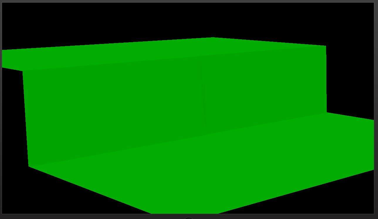
Most of this is exactly as it was in the provided sample code. All we’ve done is add the height map and a sampler to read it with, set the y-value of the vertex position to the value stored in the height map, and change the colour pass through to a (u, v) texture coordinate.
With no other changes to our shaders and initializing the height map to have some visible variation, we get this:
Now that we have our mesh being displaced by our height map, we need to add some basic shading to the Pixel Shader. As I mentioned before, we’ll use the texture coordinates to look up the height value and calculate a per-pixel normal. We’re going to hard code a light source and use a simple ambient and diffuse lighting model.
// Per-pixel color data passed through the pixel shader.
struct PixelShaderInput
{
min16float4 pos : SV_POSITION;
min16float2 uv : TEXCOORD0;
};
Texture2D<float> heightmap : register(t0);
SamplerState hmsampler : register(s0) {
Filter = MIN_MAG_MIP_LINEAR;
};
float3 estimateNormal(float2 texcoord) {
float2 b = texcoord + float2(0.0f, -0.01f);
float2 c = texcoord + float2(0.01f, -0.01f);
float2 d = texcoord + float2(0.01f, 0.0f);
float2 e = texcoord + float2(0.01f, 0.01f);
float2 f = texcoord + float2(0.0f, 0.01f);
float2 g = texcoord + float2(-0.01f, 0.01f);
float2 h = texcoord + float2(-0.01f, 0.0f);
float2 i = texcoord + float2(-0.01f, -0.01f);
float zb = heightmap.SampleLevel(hmsampler, b, 0).x;
float zc = heightmap.SampleLevel(hmsampler, c, 0).x;
float zd = heightmap.SampleLevel(hmsampler, d, 0).x;
float ze = heightmap.SampleLevel(hmsampler, e, 0).x;
float zf = heightmap.SampleLevel(hmsampler, f, 0).x;
float zg = heightmap.SampleLevel(hmsampler, g, 0).x;
float zh = heightmap.SampleLevel(hmsampler, h, 0).x;
float zi = heightmap.SampleLevel(hmsampler, i, 0).x;
float x = zg + 2 * zh + zi - zc - 2 * zd - ze;
float y = 2 * zb + zc + zi - ze - 2 * zf - zg;
float z = 8.0f;
return normalize(float3(x, y, z));
}
// The pixel shader passes through the color data. The color data from
// is interpolated and assigned to a pixel at the rasterization step.
min16float4 main(PixelShaderInput input) : SV_TARGET {
float3 color = { 0.0f, 1.0f, 0.0f };
float3 norm = estimateNormal(input.uv);
float3 light = normalize(float3(1.0f, 1.0f, -1.0f));
float diff = saturate(dot(norm, -light));
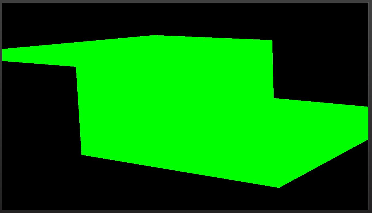
return min16float4(saturate(color * (diff + 0.1f)), 1.0f);
}
With this implemented, the previous image comes out looking like so:

This is all pretty boring, and potentially repetitive if you read any of my Rendering Terrain posts, but now that we have this set up, we can move on to much more interesting stuff1. Next post, I’ll be talking about how I’m procedurally generating the terrain.
For the latest code, visit GitHub.
Traagen