Before moving on to Cascaded Shadow Maps, I decided to work on improving the existing shadows. I figured it would be prudent to get the basic shadow map looking as presentable as I could prior to going to a more complicated system. To that end, I added a skirt to the terrain, turning it into an enclosed 3D surface, played with depth bias to try and deal with shadow acne, and attempted to address the shimmering shadows.
Adding a Skirt
Adding a skirt to the terrain turned out to be an interesting affair. And when I say interesting, I mean a pain in the ass. My shaders weren’t written in a way that allowed them to automatically deal with the skirt, so I had to make a few modifications to get things working. And just figuring out the ordering of indices to make sure our patches were facing the right way was a bit of a headache too.
The first order of business was to define a base height which will always be below the lowest height value in the terrain. Of course, the way we are currently loading our terrains, the lowest height value in the terrain will never be less than zero, so any negative value will do. But if I change the height map loading code, I’d like to not have to modify the skirt code. So to that end, I said let’s find the minimum value currently in the height map and subtract ten from it. Luckily, we already have a function that will find the minimum value. We use it to define values for our frustum culling. Subtracting ten is arbitrary, but I wanted to make sure I have a value that wasn’t likely to cause any z-fighting issues in the shadow map.
mBaseHeight = (int)(CalcZBounds(maVertices[0], maVertices[numVertsInTerrain - 1]).x - 10);
Now that we know where the base of the skirt will be, we can add the vertices that make up that base. We need to add one vertex for each vertex along the edge of the terrain. So for a 2048×2048 height map, we’re adding 512 vertices per edge. We don’t need to add any vertices for the very bottom plane of the skirt. It will be completely flat, so using the four corner vertices will work fine.
// create base vertices for side 1 of skirt. y = 0.
int iVertex = numVertsInTerrain;
for (int x = 0; x < scalePatchX; ++x) {
	maVertices[iVertex].position = XMFLOAT3(x * tessFactor, 0.0f, mBaseHeight);
	maVertices[iVertex++].tex = XMFLOAT3((float)x / (float)scalePatchX, 0.0f, 1.0f);
}

// create base vertices for side 2 of skirt. y = mDepth - tessFactor.
for (int x = 0; x < scalePatchX; ++x) {
	maVertices[iVertex].position = XMFLOAT3(x * tessFactor, mDepth - tessFactor, mBaseHeight);
	maVertices[iVertex++].tex = XMFLOAT3((float)x / (float)scalePatchX, (float)(mDepth - tessFactor) / (float)mDepth, 2.0f);
}

// create base vertices for side 3 of skirt. x = 0.
for (int y = 0; y < scalePatchY; ++y) {
	maVertices[iVertex].position = XMFLOAT3(0.0f, y * tessFactor, mBaseHeight);
	maVertices[iVertex++].tex = XMFLOAT3(0.0f, (float)y / (float)scalePatchY, 3.0f);
}

// create base vertices for side 4 of skirt. x = mWidth - tessFactor.
for (int y = 0; y < scalePatchY; ++y) {
	maVertices[iVertex].position = XMFLOAT3(mWidth - tessFactor, y * tessFactor, mBaseHeight);
	maVertices[iVertex++].tex = XMFLOAT3((float)(mWidth - tessFactor) / (float)mWidth, (float)y / (float)scalePatchY, 4.0f);
}
If you’re wondering about the mDepth – tessFactor values, this is because of how I have things defined. If our height map is 2048×2048 and our tessFactor=4, then our scalePatchX and scalePatchY are 512. So our loops go from 0 to 511, which actually scales to 0 to 2044.
A lot of the time height maps are defined as 2N+1×2N+1 instead of 2Nx2N as we currently have. In that case, you actually get a much cleaner function because you can add a vertex. A 2049×2049 height map would have a mesh with dimensions 513×513. Essentially, you would subtract one from the height map width to get the terrain width, which means you get to use all the values in the height map, instead of losing a few off the end like we currently do. That’s no big deal for this project, but I’ll definitely want to fix it in future projects.
Now that we’ve defined all of our extra skirt vertices, we can define the new indices. In order to get the patches facing in the correct direction, I had to experiment a bit. The patches are also upside down. This is because we define the AABB values needed for frustum culling on a per patch basis and save it into the 0th control point. But since we’ve already done that for all the vertices in the existing terrain and we are going to be re-using the edge vertices in the skirt, we don’t want to overwrite any of those values. So we flip the patch over so we can store the AABB values for each skirt value in an unused vertex. I had to map out a bit which vertices were used when choosing the order for the base plane for the same reason.
// so as not to interfere with the terrain wrt bounds for frustum culling, we need the 0th control point of each skirt patch to be a base vertex as defined above.
// add indices for side 1 of skirt. y = 0.
iVertex = numVertsInTerrain;
for (int x = 0; x < scalePatchX - 1; ++x) {
	maIndices[i++] = iVertex;		// control point 0
	maIndices[i++] = iVertex + 1;	// control point 1
	maIndices[i++] = x;				// control point 2
	maIndices[i++] = x + 1;			// control point 3
	XMFLOAT2 bz = CalcZBounds(maVertices[x], maVertices[x + 1]);
	maVertices[iVertex].aabbmin = XMFLOAT3(x * tessFactor, 0.0f, mBaseHeight);
	maVertices[iVertex++].aabbmax = XMFLOAT3((x + 1) * tessFactor, 0.0f, bz.y);
}
// add indices for side 2 of skirt. y = mDepth - tessFactor.
++iVertex;
for (int x = 0; x < scalePatchX - 1; ++x) {
	maIndices[i++] = iVertex + 1;
	maIndices[i++] = iVertex;
	int offset = scalePatchX * (scalePatchY - 1);
	maIndices[i++] = x + offset + 1;
	maIndices[i++] = x + offset;
	XMFLOAT2 bz = CalcZBounds(maVertices[x + offset], maVertices[x + offset + 1]);
	maVertices[++iVertex].aabbmin = XMFLOAT3(x * tessFactor, mDepth - tessFactor, mBaseHeight);
	maVertices[iVertex].aabbmax = XMFLOAT3((x + 1) * tessFactor, mDepth - tessFactor, bz.y);
}
// add indices for side 3 of skirt. x = 0.
++iVertex;
for (int y = 0; y < scalePatchY - 1; ++y) {
	maIndices[i++] = iVertex + 1;
	maIndices[i++] = iVertex;
	maIndices[i++] = (y + 1) * scalePatchX;
	maIndices[i++] = y * scalePatchX;
	XMFLOAT2 bz = CalcZBounds(maVertices[y * scalePatchX], maVertices[(y + 1) * scalePatchX]);
	maVertices[++iVertex].aabbmin = XMFLOAT3(0.0f, y * tessFactor, mBaseHeight);
	maVertices[iVertex].aabbmax = XMFLOAT3(0.0f, (y + 1) * tessFactor, bz.y);
}
// add indices for side 4 of skirt. x = mWidth - tessFactor.
++iVertex;
for (int y = 0; y < scalePatchY - 1; ++y) {
	maIndices[i++] = iVertex;
	maIndices[i++] = iVertex + 1;
	maIndices[i++] = y * scalePatchX + scalePatchX - 1;
	maIndices[i++] = (y + 1) * scalePatchX + scalePatchX - 1;
	XMFLOAT2 bz = CalcZBounds(maVertices[y * scalePatchX + scalePatchX - 1], maVertices[(y + 1) * scalePatchX + scalePatchX - 1]);
	maVertices[iVertex].aabbmin = XMFLOAT3(mWidth - tessFactor, y * tessFactor, mBaseHeight);
	maVertices[iVertex++].aabbmax = XMFLOAT3(mWidth - tessFactor, (y + 1) * tessFactor, bz.y);
}
// add indices for bottom plane.
maIndices[i++] = numVertsInTerrain + scalePatchX - 1;
maIndices[i++] = numVertsInTerrain;
maIndices[i++] = numVertsInTerrain + scalePatchX + scalePatchX - 1;
maIndices[i++] = numVertsInTerrain + scalePatchX;
maVertices[numVertsInTerrain + scalePatchX - 1].aabbmin = XMFLOAT3(0.0f, 0.0f, mBaseHeight);
maVertices[numVertsInTerrain + scalePatchX - 1].aabbmax = XMFLOAT3(mWidth, mDepth, mBaseHeight);
maVertices[numVertsInTerrain + scalePatchX - 1].tex.z = 0.0f;
I haven’t really touched much on the mesh building code in a while. It’s changed quite a bit since I first introduced it in Part 4. I didn’t really touch too much on the changes when I added Tessellation, Level of Detail, or Frustum Culling.
Our vertices were made up of a (x, y, z) position, a (u, v) texture coordinate, and a (min, max) z-bounds value. To get the skirt to work, we’ve had to add to that a bit.
The z-bounds value was used in our frustum culling code in conjunction with the (x, y) coordinates of the control points of the patch to define the bounding box. That code depended on the 0th control point being minimum and the 3rd (still 0-based) being the max.
// build axis-aligned bounding box.
// ip[0] is lower left corner
// ip[3] is upper right corner
// get z value from boundsZ variable. Correct value will be in ip[0].
float3 vMin = float3(ip[0].worldpos.x, ip[0].worldpos.y, ip[0].boundsZ.x);
float3 vMax = float3(ip[3].worldpos.x, ip[3].worldpos.y, ip[0].boundsZ.y);
That isn’t true for our new skirt patches. They are vertical and upside down. So we now need to fully define our bounding boxes in the 0th control point. We now send a (x, y, z) value for the minimum and for the maximum bounds of the AABB.
I also ran into problems with tessellation when it comes to the skirt. Ideally, we don’t want to tessellate the skirt at all, but we need to at least tessellate the edge that is shared with the terrain itself or we would get cracks. The bottom plane definitely doesn’t need to be tessellated. So now we need a way to identify whether a patch is on the side skirts, the bottom plane, or the terrain. To that end, I added a third value to the texture coordinates. I defined the bottom plane as 0, each side skirt as 1-4 (in case I need to identify a specific side in the future), and the terrain as 5.
In my Hull Shaders, I’m now able to identify which piece of the mesh I’m looking at and tessellate accordingly. I don’t tessellate the bottom plane at all and I only tessellate the one connected edge of the side skirts.
if (aabbOutsideFrustumTest(boxCenter, boxExtents, frustum)) {
	output.EdgeTessFactor[0] = 0.0f;
	output.EdgeTessFactor[1] = 0.0f;
	output.EdgeTessFactor[2] = 0.0f;
	output.EdgeTessFactor[3] = 0.0f;
	output.InsideTessFactor[0] = 0.0f;
	output.InsideTessFactor[1] = 0.0f;

	return output;
} else {
	// don't tessellate any part of the skirt that isn't directly touching the terrain.
	if (ip[0].tex.z == 0.0f) {
		output.EdgeTessFactor[0] = 1.0f;
		output.EdgeTessFactor[1] = 1.0f;
		output.EdgeTessFactor[2] = 1.0f;
		output.EdgeTessFactor[3] = 1.0f;
		output.InsideTessFactor[0] = 1.0f;
		output.InsideTessFactor[1] = 1.0f;

		return output;
	} else if (ip[0].tex.z < 5.0f) {
		float3 e3 = 0.5f * (ip[2].worldpos + ip[3].worldpos);

		output.EdgeTessFactor[0] = 1.0f;
		output.EdgeTessFactor[1] = 1.0f;
		output.EdgeTessFactor[2] = 1.0f;
		output.EdgeTessFactor[3] = CalcTessFactor(e3);
		output.InsideTessFactor[0] = 1.0f;
		output.InsideTessFactor[1] = 1.0f;

		return output;
	}
	// tessellate based on distance from the camera.
	// compute tess factor based on edges.
	// compute midpoint of edges.
	float3 e0 = 0.5f * (ip[0].worldpos + ip[2].worldpos);
	float3 e1 = 0.5f * (ip[0].worldpos + ip[1].worldpos);
	float3 e2 = 0.5f * (ip[1].worldpos + ip[3].worldpos);
	float3 e3 = 0.5f * (ip[2].worldpos + ip[3].worldpos);
	float3 c = 0.25f * (ip[0].worldpos + ip[1].worldpos + ip[2].worldpos + ip[3].worldpos);

	output.EdgeTessFactor[0] = CalcTessFactor(e0);
	output.EdgeTessFactor[1] = CalcTessFactor(e1);
	output.EdgeTessFactor[2] = CalcTessFactor(e2);
	output.EdgeTessFactor[3] = CalcTessFactor(e3);
	output.InsideTessFactor[0] = CalcTessFactor(c);
	output.InsideTessFactor[1] = output.InsideTessFactor[0];

	return output;
}
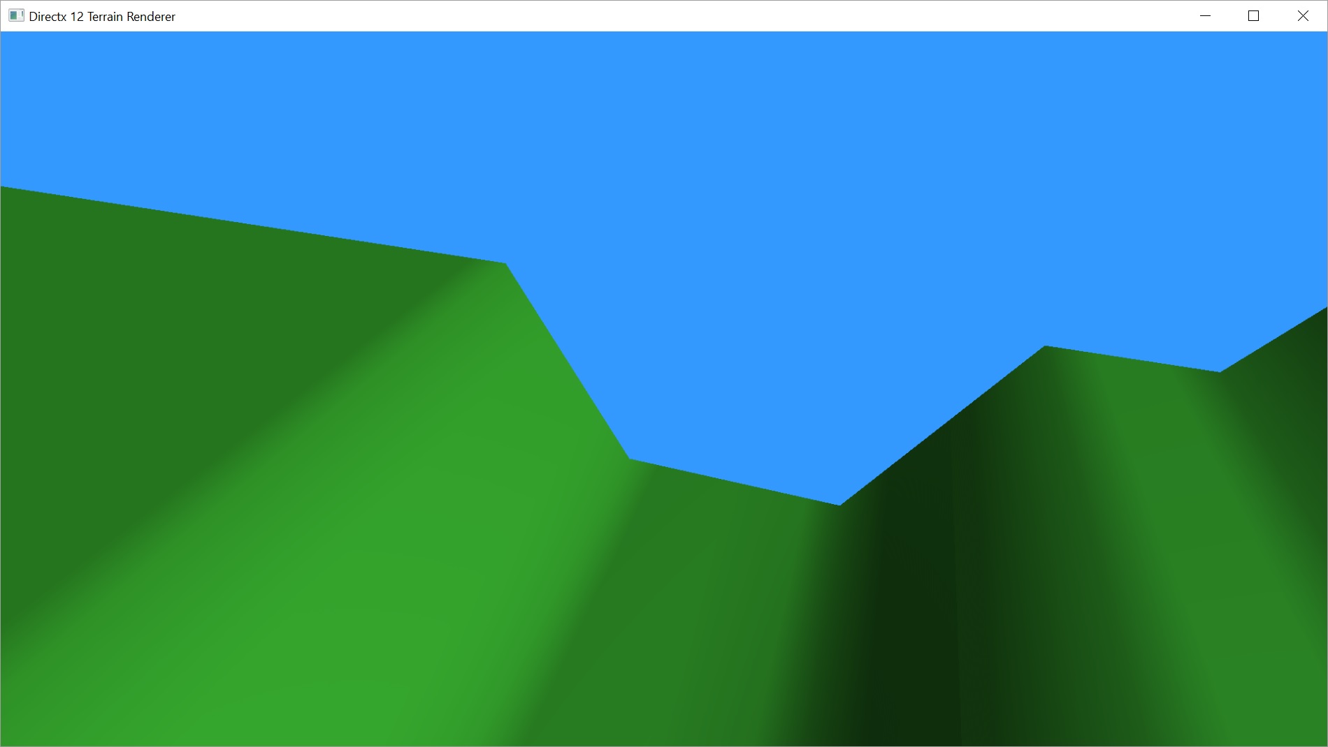
This pretty much did what I wanted, but there was one little glitchy issue that cropped up along the edges. Odd little polygons were popping up along the edge, sticking out above the terrain, as if the skirt edges weren’t being tessellated to match the terrain edge.

It’s kind of hard to make out, but the circled area is a polygon sticking up from the skirt that doesn’t match the terrain.
At first, I didn’t know what was going on, but after reading about tessellation for a bit, I realized I was still tessellating my skirt patches, even though I had set the tessellation factors to one, which should be none. The reason being that I am using the partitioning value “fractional_even”, which actually has a range of 2-64. This gives me the maximum possible tessellation for my terrain, where “fractional_odd” would give me 1-63 and probably fix my problem at the slight loss of resolution. The other possible value, “integer” has a range of 1-64, but does not interpolate between values, so I’d wind up with popping terrain.
The only reason the tessellation is a problem is because my Domain Shaders move the z-position of our vertices based on the height map. If it just linearly interpolated the values of the vertices that don’t border the terrain, we wouldn’t have a problem. Here comes that skirt value, to the rescue again.
if (input.skirt < 5) {
	if (input.skirt > 0 && domain.y == 1) {
		output.worldpos.z = heightmap.SampleLevel(hmsampler, tex, 0.0f) * scale;
	}
} else {
	output.worldpos.z = heightmap.SampleLevel(hmsampler, tex, 0.0f) * scale;
}
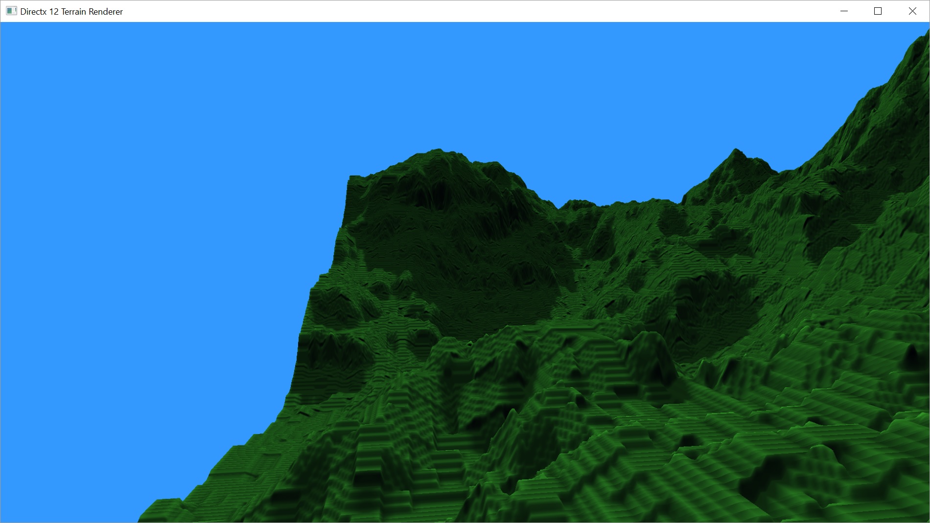
That fixed the issue with the weird edges sticking up because the edges that were actually causing the problem were not the bordering edge. That edge matches the terrain edge exactly. Now the other edges are minimally tessellated and stay where they should.
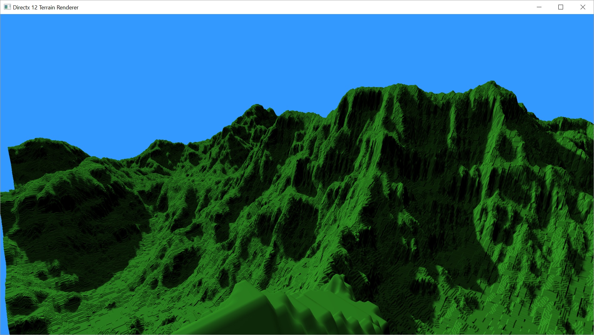
All good again.
So this solves a couple of issues I mentioned last post. I can now use back-face culling, as Microsoft recommends, without the Sun shining through the back of the terrain. This solves a problem I had where there was too much light in the shadowed areas. It does, however, introduce the problem of shadow acne, which hadn’t been much of an issue with front-face culling. We’ll talk about that problem next.
Shadow Acne and Depth Bias
Shadow acne is caused by sampling a limited resolution shadow map that can’t possibly contain every possible value for the terrain. This article describes it pretty well. As I mentioned last post, I didn’t have shadow acne when I was using front-face culling, as is recommended in this GameDev.net forum topic pretty adamantly. But I also had a completely different problem that I simply couldn’t fix with either depth bias or the related normal offset bias, no matter what values I tried. Back-face culling fixed that problem completely, but introduced the shadow acne big time.
I couldn’t find much online about how to set depth bias values, besides a quick blurb by Microsoft. It contains a formula that applies to me, but I wasn’t sure how to use it.
Bias = (float)DepthBias * r + SlopeScaledDepthBias * MaxDepthSlope;
where r is the minimum representable value > 0 in the depth-buffer format converted to float32. The DepthBias and SlopeScaledDepthBias values are D3D11_RASTERIZER_DESC1 structure members. The MaxDepthSlope value is the maximum of the horizontal and vertical slopes of the depth value at the pixel.
My problem being that I don’t really know what r or MaxDepthSlope actually are.
Frank Luna’s book that I’m always harping on about actually clarified things quite a bit for me.
For a 24-bit depth buffer, r = 1 / 2^24.
Example: DepthBias = 100000 ==> Actual DepthBias = 100000/2^24 = .006
That little bit helped a lot, actually. He doesn’t clarify the slope scaled bias stuff, but the basic depth bias is easier to understand now. But it still basically comes down to trial and error. And those values may very well look like shit on a different terrain. Awesome.
I eventually settled on values that eliminated the majority of the shadow acne and gave me decent shadows.
descPSO.RasterizerState.DepthBias = 25000;
descPSO.RasterizerState.DepthBiasClamp = 0.0f;
descPSO.RasterizerState.SlopeScaledDepthBias = 3.5f;

Not perfect, but not terrible either.
Shimmering Shadows
The shimmering Shadows problem is an interesting one because there are actually two different problems.
- The camera moves, causing the shadows to shimmer because the movement of the view frustum changes the positioning of the shadows in the shadow map.
- The light itself moves, causing the same damn thing.
The problem is that the most recommended solution only actually helps the first one. No one seems to have a good solution to the second.
The Camera Moves
This may be a little dry as I didn’t take any pictures or video that shows this in action prior to fixing it; but it’s the most common one, so there is tons out there about it. Microsoft briefly explains how to fix the problem, but the code they provide is completely out of context. This GameDev.net topic does a much better job of explaining it and is the basis for my own work.
In Part 13, I had talked about changing the bounding sphere for the scene to a bounding box in order to get a tighter frustum, but it turns out that I had already implemented part of the fix for shimmering shadows. The idea is that a bounding sphere is rotation invariant, meaning you get the same sized shadow frustum no matter what angle you are at. Great. That means less work for me.
The other issue was this idea of moving the light in texel-sized increments. I implemented the exact code in the GameDev.net topic, so you may as well just look at it.
Surprisingly, it made absolutely no difference to my shimmering shadows. So the shimmering shadow fix didn’t fix the shimmering shadows? Now what?
Well, it turns out that my shimmering shadows are a completely different problem that nobody had mentioned, because it’s actually the dynamic level of detail system that’s causing it. As I move about the map, the Hull Shader calculates how much to tessellate each edge by.
float CalcTessFactor(float3 p) {
	float d = distance(p, eye);

	float s = saturate((d - 16.0f) / (256.0f - 16.0f));
	return pow(2, (lerp(6, 0, s)));
}
Both the shadow map and normal rendering pass were using the same values. The near cut off is at 16m and the far cut off at 256m. I tried changing the near cut off to 32m. The result was less shimmering up close, but still plenty further away. Also, it hurt my frame rate a bit.
So then I tried setting the shadow map to 16m but the normal pass to 32m. I still wound up with the original amount of shimmering. So it appeared to be the tessellation in the shadow map that causes the problem.
With the current state of the terrain, I can definitely use a lower tessellation value and not lose detail. This may change in the future, but for now let’s change those values more aggressively.
float CalcTessFactor(float3 p) {
	float d = distance(p, eye);

	float s = saturate((d - 128.0f) / (256.0f - 128.0f));
	return pow(2, (lerp(4, 0, s)));
}
So now we put the near cut off much further away, but we also reduce the maximum tessellation from 64 (26) to 16 (24). That actually still means we’re subdividing our original patches to a smaller value than our height map contains, so we’re definitely still good.
This all but eliminated the shimmering due to moving the camera around. If you look into the distance a bit, you can still see when the LOD switches, but it’s fairly far out and in practice you’re likely to be focused on the area around you.
As it turns out, I don’t need the code to move the light in texel-sized increments. I commented it out and there was no change. I’ll leave the commented code in just in case I need it later, but at the moment it is a waste of CPU cycles.
The Light Moves
This one is still a pretty big issue for me. I originally thought Cascaded Shadow Maps would be the solution, and I’m still going to implement it and see how it affects my shadows, but everything I’ve been reading indicates that there is no good solution to this problem.
This blog post by Phil Fortier of Ice Fall Games seems to be the only real solution presented anywhere that I could find. His solution is to render two shadow maps from slightly different light positions and blend them together. He seems to indicate that he builds both shadow maps new each frame. He does discuss alternating building the two shadow maps, one per frame, but sounds like he hadn’t tried that at the time of posting.
My thoughts on what he is suggesting would be to keep two shadow maps and alternate which one you render to on each frame. You can then blend the previous frame with the current frame. You still have the added expense in terms of memory and PCF-taps, but you don’t add any extra rendering passes for your scene.
I’m going to implement Cascaded Shadow Maps first, but I may come back to this idea if/when CSM doesn’t fix my shimmering problems. I’m not sure if I’d even need to duplicate the entire cascade. The shimmering is somewhat noticeable at a distance, but it is much more of an issue up close. I may be able to optimize and not blend the background shadows.
A quick note about performance before I end this post. Because I wound up reducing the overall tessellation on the shadow map pass, our frame rate has improved from 5.7ms, 175fps, to 5.1ms, 197fps on our 2048×2048 height map with a 2048×2048 shadow map.
And we’ll add a video showing the current state as well.
The latest code is available on GitHub.
Traagen